Mitsubishi Montero Sport (2004+). Manual - part 272


  Index      Mitsubishi     Mitsubishi Montero Sport - service repair manual 2004 year


Search            


Content   ..  270  271  272  273   ..


Mitsubishi Montero Sport (2004+). Manual - part 272


MULTIPORT FUEL INJECTION (MFI) DIAGNOSIS

TSB Revision

MULTIPORT FUEL INJECTION (MFI)

13A-501

DIAGNOSIS

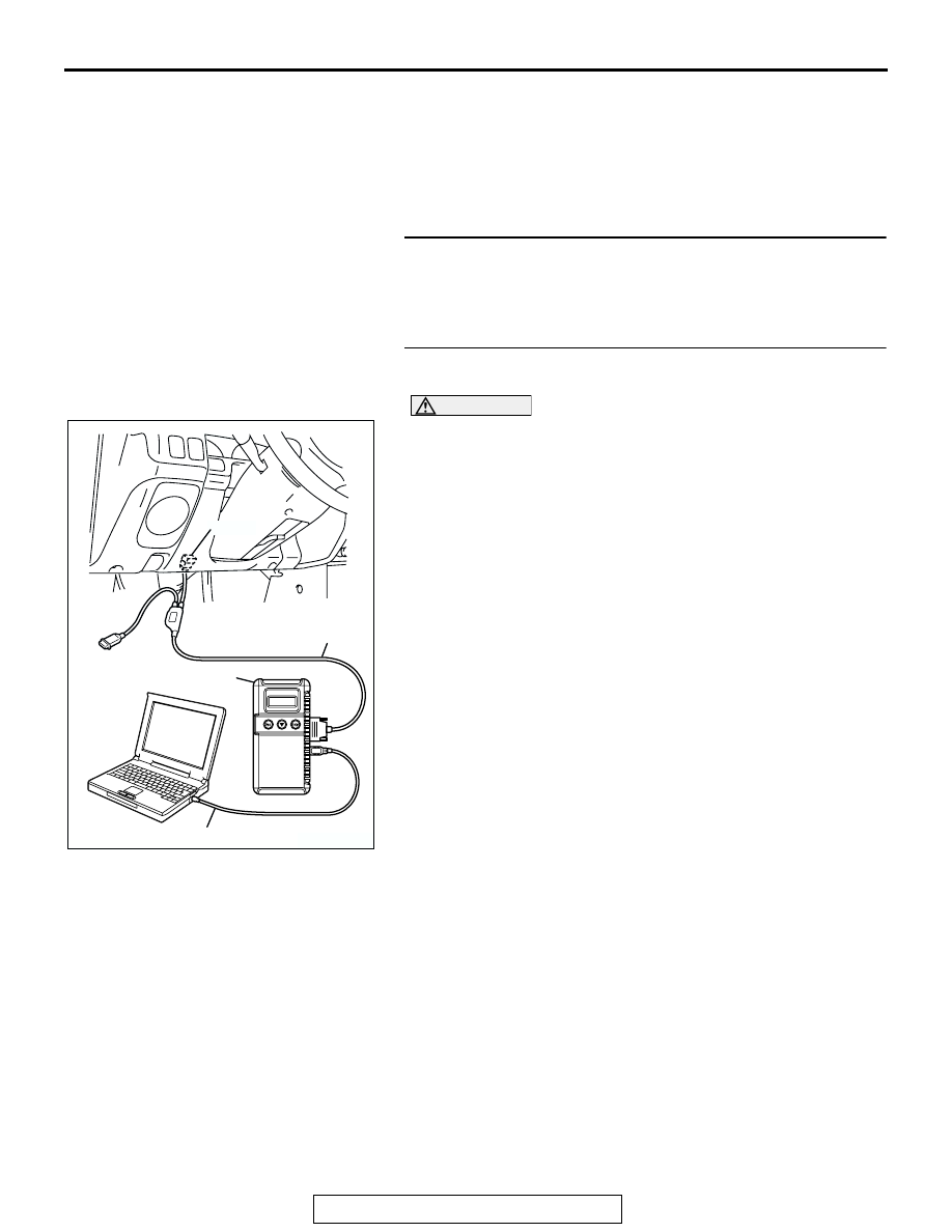
Required Special Tools:

• MB991958: Scan Tool (MUT-III Sub Assembly)

• MB991824: V.C.I

• MB991827: USB Cable

• MB991911: Main Harness B

STEP 1. Check for exhaust leaks.
Q: Are there any abnormalities?

YES : Go to Step 2.
NO :  Repair it. Then go to Step 7.

STEP 2. Using scan tool MB991958, check data list item 59: 
Heated Oxygen Sensor Bank 2, Sensor 2 (left rear).

CAUTION

To prevent damage to scan tool MB991958, always turn the 
ignition switch to the "LOCK" (OFF) position before con-
necting or disconnecting scan tool MB991958.
(1) Connect scan tool MB991958 to the data link connector.
(2) Start the engine and run at idle.
(3) Set scan tool MB991958 to the data reading mode for item 

59, Heated Oxygen Sensor Bank 2, Sensor 2 (left rear).

• Warm up the engine. When the engine is revved, the 

output voltage should repeat 0 volt and 0.6 to 1.0 volt 
alternately.

(4) Turn the ignition switch to the "LOCK" (OFF) position.
Q: Is the sensor operating properly?

YES : Go to Step 3.
NO :  Refer to DTC P0156 

− Heated Oxygen Sensor Circuit 

(bank 2, sensor 2) 

P.13A-327

,DTC P0157 

− Heated 

Oxygen Sensor Circuit Low Voltage (bank 2, sensor 
2) 

P.13A-340

, DTC P0158 

− Heated Oxygen Sensor 

Circuit High Voltage (bank 2, sensor 2) 

P.13A-349

DTC P0159 

− Heated Oxygen Sensor Circuit Slow 

Response (bank 2, sensor 2) 

P.13A-355

.

AK303629AB

MB991911

MB991827

MB991824 

16-PIN

MULTIPORT FUEL INJECTION (MFI) DIAGNOSIS

TSB Revision

MULTIPORT FUEL INJECTION (MFI)

13A-502

STEP 3. Using scan tool MB991958, check data list item 11: 
Heated Oxygen Sensor Bank 2, Sensor 1 (left front).
(1) Start the engine and run at idle.
(2) Set scan tool MB991958 to the data reading mode for item 

11, Heated Oxygen Sensor Bank 2, Sensor 1 (left front).

• Warm up the engine. When the engine is revved, the 

output voltage should measure 0.6 to 1.0 volt.

(3) Turn the ignition switch to the “LOCK” (OFF) position.
Q: Is the sensor operating properly?

YES : Go to Step 4.
NO :  Refer to DTC P0150 

− Heated Oxygen Sensor Circuit 

(bank 2, sensor 2) 

P.13A-275

, DTC P0151 

− Heated 

Oxygen Sensor Circuit low voltage (bank 1, sensor 2) 

P.13A-287

, P0152 

− Heated Oxygen Sensor Circuit 

High Voltage (bank 2, sensor 1) 

P.13A-295

, DTC 

P0153 

− Heated Oxygen Sensor Circuit Slow 

Response (bank 2, sensor 1) 

P.13A-300

, DTC P0154 

− Heated Oxygen Sensor NO Activity Detected (bank 

2, sensor 1) 

P.13A-306

.

STEP 4. Using scan tool MB991958, check data list item 11: 
Heated Oxygen Sensor Bank 2, Sensor 1 (left front).
(1) Start the engine and run at idle.
(2) Set scan tool MB991958 to the data reading mode for item 

11, Heated Oxygen Sensor Bank 2, Sensor 1 (left front).

(3) Keep the engine speed at 2,000 r/min.

• 0 − 0.4 and 0.6 − 1.0 volt should alternate 15 times or 

more within 10 seconds.

(4) Turn the ignition switch to the "LOCK" (OFF) position.
Q: Is the sensor operating properly?

YES : Go to Step 5.
NO :  Replace the left bank heated oxygen sensor (front). 

Then go to Step 7.

AK303629AB

MB991911

MB991827

MB991824 

16-PIN

AK303629AB

MB991911

MB991827

MB991824 

16-PIN

MULTIPORT FUEL INJECTION (MFI) DIAGNOSIS

TSB Revision

MULTIPORT FUEL INJECTION (MFI)

13A-503

STEP 5. Test the OBD-II drive cycle.
(1) Carry out a test drive with the drive cycle pattern. Refer to 

Diagnostic Function 

− OBD-II Drive Cycle − Procedure 3 − 

Catalytic Converter Monitor 

P.13A-4

.

(2) Check the diagnostic trouble code (DTC).
Q: Is DTC P0431 set?

YES : Replace the left bank side catalytic converter. Then 

go to Step 6.

NO :  The procedure is complete.

STEP 6. Test the OBD-II drive cycle.
(1) Carry out a test drive with the drive cycle pattern. Refer to 

Diagnostic Function 

− OBD-II Drive Cycle − Procedure 3 − 

Catalytic Converter Monitor 

P.13A-4

.

(2) Check the diagnostic trouble code (DTC).
Q: Is DTC P0431 set?

YES : Replace the PCM. Then go to Step 7.
NO :  The procedure is complete.

STEP 7. Test the OBD-II drive cycle.
(1) Carry out a test drive with the drive cycle pattern. Refer to 

Diagnostic Function 

− OBD-II Drive Cycle − Procedure 3 − 

Catalytic Converter Monitor 

P.13A-4

.

(2) Check the diagnostic trouble code (DTC).
Q: Is DTC P0431 set?

YES : Repeat the troubleshooting.
NO :  The procedure is complete.

MULTIPORT FUEL INJECTION (MFI) DIAGNOSIS

TSB Revision

MULTIPORT FUEL INJECTION (MFI)

13A-504

DTC P0441: Evaporative Emission Control System Incorrect Purge Flow

.

TECHNICAL DESCRIPTION

• PCM detects stuck open of evaporative emission 

purge solenoid valve and stuck close of evapora-
tive emission ventilation solenoid valve by pres-
sure change in fuel tank.

• Stuck open of evaporative emission purge sole-

noid valve is judged through monitoring leak of 
evaporative emission system.

• Stuck close of evaporative emission ventilation 

solenoid valve is judged after 20 seconds of end 
of monitoring leak of evaporative emission sys-
tem, or of usual operation of evaporative emis-
sion purge solenoid from ON to OFF.

.

DESCRIPTIONS OF MONITOR METHODS
Fuel tank pressure decreases largely during 

purge-cut.

.

MONITOR EXECUTION
Continuous

.

MONITOR EXECUTION CONDITIONS (Other 
monitor and Sensor)

Other Monitor (There is no temporary DTC stored 

in memory for the item monitored below)

• Fuel tank pressure sensor monitor

Sensor (The sensor below is determined to be 

normal)

• Not applicable

.

AK200026AB

CONNECTOR: A-10

EVAPORATIVE EMISSION
PURGE SOLENOID

A-10(B)

AK200181

CONNECTOR: E-63

AB

E-63(B)

EVAPORATIVE EMISSION
VENTILATION SOLENOID


Content   ..  270  271  272  273   ..