Mitsubishi Montero Sport (2004+). Manual - part 232
MULTIPORT FUEL INJECTION (MFI) DIAGNOSIS
TSB Revision
MULTIPORT FUEL INJECTION (MFI)
13A-341
.
CIRCUIT OPERATION
• A voltage corresponding to the oxygen concen-
tration in the exhaust gas is sent to the PCM (ter-
minal No. 73) from the output terminal (terminal
No. 4) of the left bank heated oxygen sensor
(rear).
• Terminal No. 2 of the left bank heated oxygen
sensor (rear) is grounded with PCM (terminal No.
57).
.
TECHNICAL DESCRIPTION
• The output signal of the left bank heated oxygen
sensor (front) is compensated by the output sig-
nal of the left bank heated oxygen sensor (rear).
• The PCM checks for an open circuit in the left
bank heated oxygen sensor (rear) output line.
.
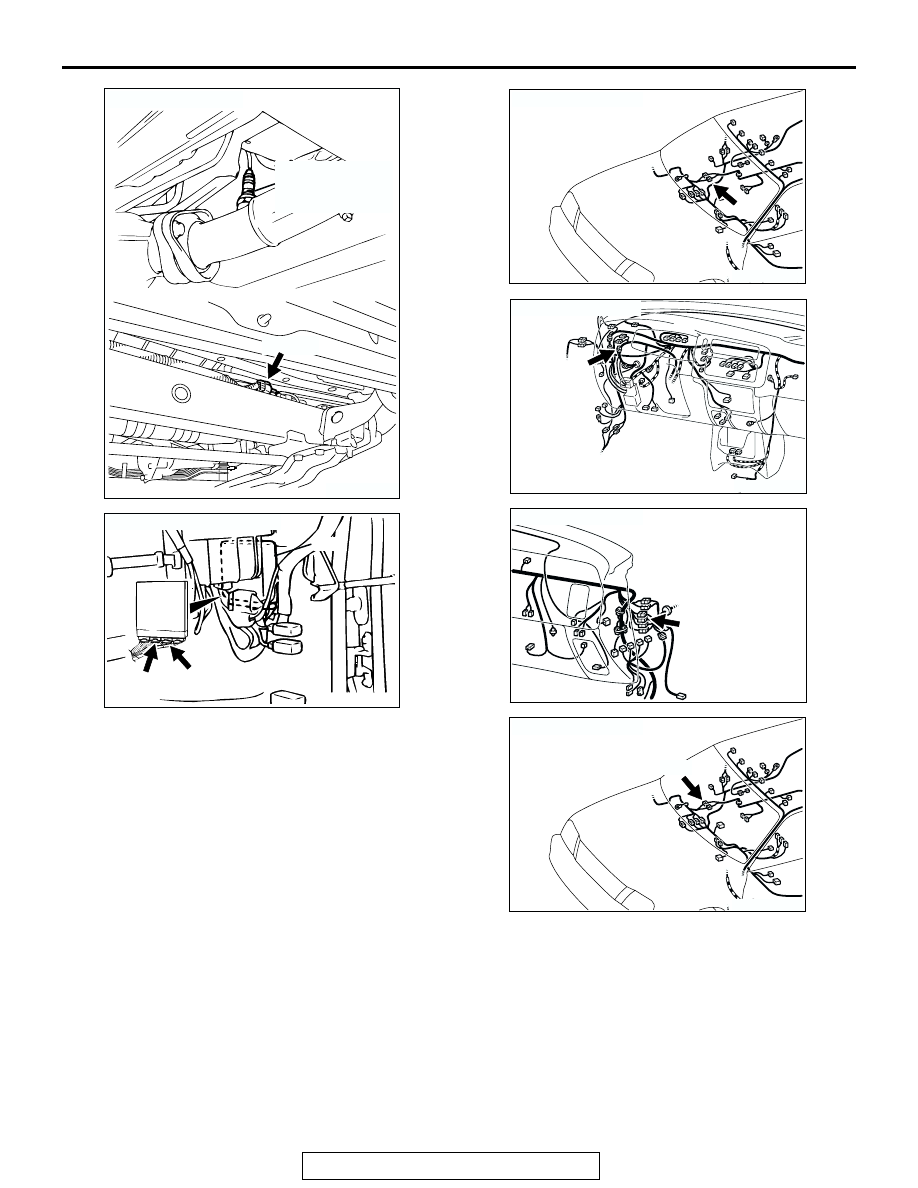
AK200497
LEFT BANK
HEATED OXYGEN
SENSOR (REAR)
E-48(B)
AB
CONNECTOR: E-48
AK103738AE
CONNECTORS: C-90, C-91
PCM
C-91(GR)
C-90(GR)
AK200018 AB
CONNECTOR: E-44
E-44
AK103912AB
CONNECTOR: C-71
C-71
AK103911AC
CONNECTOR: C-79
C-79
AK200018 AC
CONNECTOR: E-45
E-45(B)