Mitsubishi Montero Sport (2004+). Manual - part 96


  Index      Mitsubishi     Mitsubishi Montero Sport - service repair manual 2004 year


Search            


Content   ..  94  95  96  97   ..


Mitsubishi Montero Sport (2004+). Manual - part 96


STARTING SYSTEM

TSB Revision

ENGINE ELECTRICAL

16-25

FREE RUNNING TEST
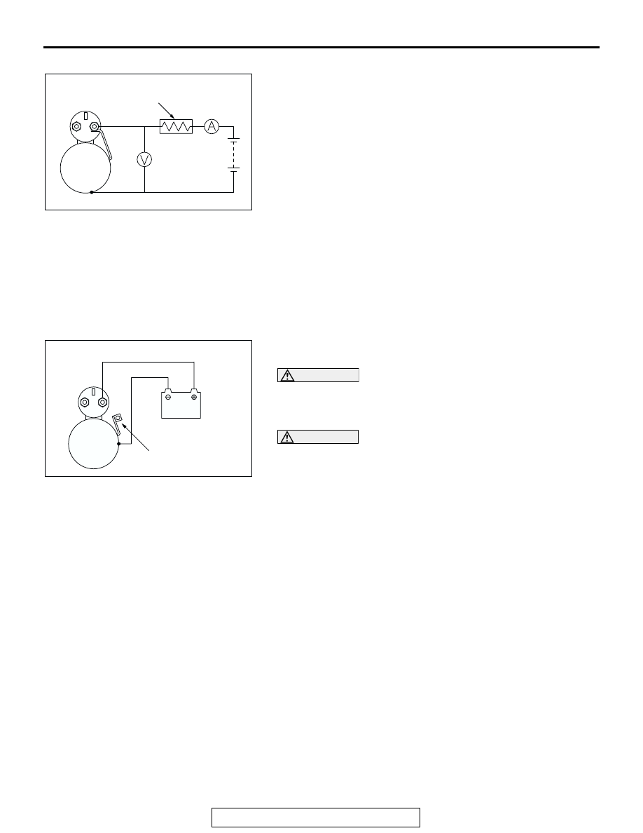
1. Place the starter motor in a vise equipped with soft jaws and 

connect a fully-charged 12-volt battery to the starter motor 
as follows:

2. Connect a test ammeter (100-ampere scale) and carbon pile 

rheostat in series between the positive battery terminal and 
starter motor terminal.

3. Connect a voltmeter (15-volt scale) across the starter motor.
4. Rotate carbon pile to full-resistance position.
5. Connect the battery cable from the negative battery terminal 

to the starter motor body.

6. Adjust the rheostat until the battery positive voltage shown 

by the voltmeter is 11 V.

7. Confirm that the maximum amperage is within the 

specifications and that the starter motor turns smoothly and 
freely.

Current: maximum 90 Amps

.

MAGNETIC SWITCH RETURN TEST
1. Disconnect the field coil wire from the M-terminal of the 

magnetic switch.

CAUTION

This test must be performed quickly (in less than 10 sec-
onds) to prevent the coil from burning.
2. Connect a 12-volt battery between the M-terminal and body.

WARNING

Be careful not to get your fingers caught when pulling 
out the pinion.

3. Pull the pinion out and release. If the pinion quickly returns 

to its original position, everything is operating properly. If it 
doesn't, replace the magnetic switch.

AKX00202

S

B

M

STARTER
MOTOR

BATTERY

AMMETER

VOLTMETER

CARBON-PILE
RHEOSTAT

AB

AKX00203

S

B

M

WIRE

STARTER
MOTOR

BATTERY

AB

STARTING SYSTEM

TSB Revision

ENGINE ELECTRICAL

16-26

DISASSEMBLY AND ASSEMBLY

M1162001200097

AK101266

2

17

18

19

20

16

14

13

21

3

15

11

12

1

4

6

8

7

9

10

AB

5

5.8 ± 1.6 N·m
52 ± 14 in-lb

5.8 ± 1.6 N·m
52 ± 14 in-lb

3.4 ± 1.0 N·m
30 ± 9 in-lb

DISASSEMBLY STEPS

1. SCREW
2. MAGNETIC SWITCH
3. SCREW
4. SCREW
5. REAR BRACKET
6. BRUSH HOLDER ASSEMBLY
7. REAR BEARING

<<A>>

8. ARMATURE
9. YOKE ASSEMBLY

<<A>>

10. BALL
11. PACKING A

12. PACKING B
13. PLATE
14. PLANETARY GEAR
15. LEVER

<<B>> >>A<<

16. SNAP RING

<<B>> >>A<<

17. STOP RING
18. OVERRUNNING CLUTCH
19. INTERNAL GEAR
20. PLANETARY GEAR HOLDER
21. FRONT BRACKET

DISASSEMBLY STEPS 

STARTING SYSTEM

TSB Revision

ENGINE ELECTRICAL

16-27

DISASSEMBLY SERVICE POINTS

.

<<A>> ARMATURE AND BALL REMOVAL

CAUTION

When removing the armature, take care not to lose the ball 
(which is used as a bearing) in the armature end.

.

<<B>> SNAP RING AND STOP RING REMOVAL
1. Press a long socket wrench of appropriate size to the stop 

ring. Then tap the socket wrench to remove the stop ring to 
the pinion gear side.

2. After removing the snap ring (by using snap-ring pliers), 

remove the stop ring and the overrunning clutch.

STARTER MOTOR PART CLEANING

1. Do not immerse parts in cleaning solvent. Immersing the 

yoke and field coil assembly and/or armature will damage 
insulation. Wipe these parts with a shop towel only.

2. Do not immerse the drive unit in cleaning solvent. 

Overrunning clutch is pre-lubricated at the factory and 
solvent will wash lubrication from the clutch.

3. The drive unit may be cleaned with a brush moistened with 

cleaning solvent and wiped dry with a shop towel.

ASSEMBLY SERVICE POINT

.

>>A<< STOP RING AND SNAP RING INSTALLATION
Using a suitable pulling tool, pull the overrunning clutch stop 
ring over the snap ring.

AKX00370

SOCKET

STOP RING

PINION GEAR

OVERRUNNING
CLUTCH

AB

AKX00371

SNAP RING

PINION GEAR

OVERRUNNING
CLUTCH

SNAP-RING
PLIERS

AB

AKX00372

STOP RING

OVERRUNNING
CLUTCH

SNAP RING

STOP 
RING

AB

STARTING SYSTEM

TSB Revision

ENGINE ELECTRICAL

16-28

INSPECTION

M1162001300061

.

COMMUTATOR CHECK
1. Place the armature on a pair of V-blocks, and check the 

deflection by using a dial gauge.

Standard value: 0.05 mm (0.002 inch)
Limit: 0.1 mm (0.004 inch)

2. Check the outer diameter of the commutator.

Standard value: 29.4 mm (1.16 inches)
Minimum limit: 28.8 mm (1.13 inches)

3. Check the depth of the undercut between segments.

Standard value: 0.5 mm (0.02 inch)
Minimum limit: 0.2 mm (0.008 inch)

.

BRUSH CHECK
1. Check the brush for roughness of the surface that contacts 

the commutator and check the brush length.Replace the 
brush holder if this measurement exceeds the limit.

Minimum limit: 7.0 mm (0.28 inch)

2. .In the case contacting surface has been corrected or the 

brush has been replaced, correct the contacting surface by 
winding sandpaper around the commutator

.

AKX00373

AKX00374

AKX00375

SEGMENT

UNDERCUT

MICA

AB

AK101390

LIMIT LENGTH

AB


Content   ..  94  95  96  97   ..