Mitsubishi Montero (2004+). Manual - part 356


  Index      Mitsubishi     Mitsubishi Montero - service repair manual 2004 year


Search            


Content   ..  354  355  356  357   ..


Mitsubishi Montero (2004+). Manual - part 356


MULTIPORT FUEL INJECTION (MFI) DIAGNOSIS

TSB Revision

MULTIPORT FUEL INJECTION (MFI)

13A-911

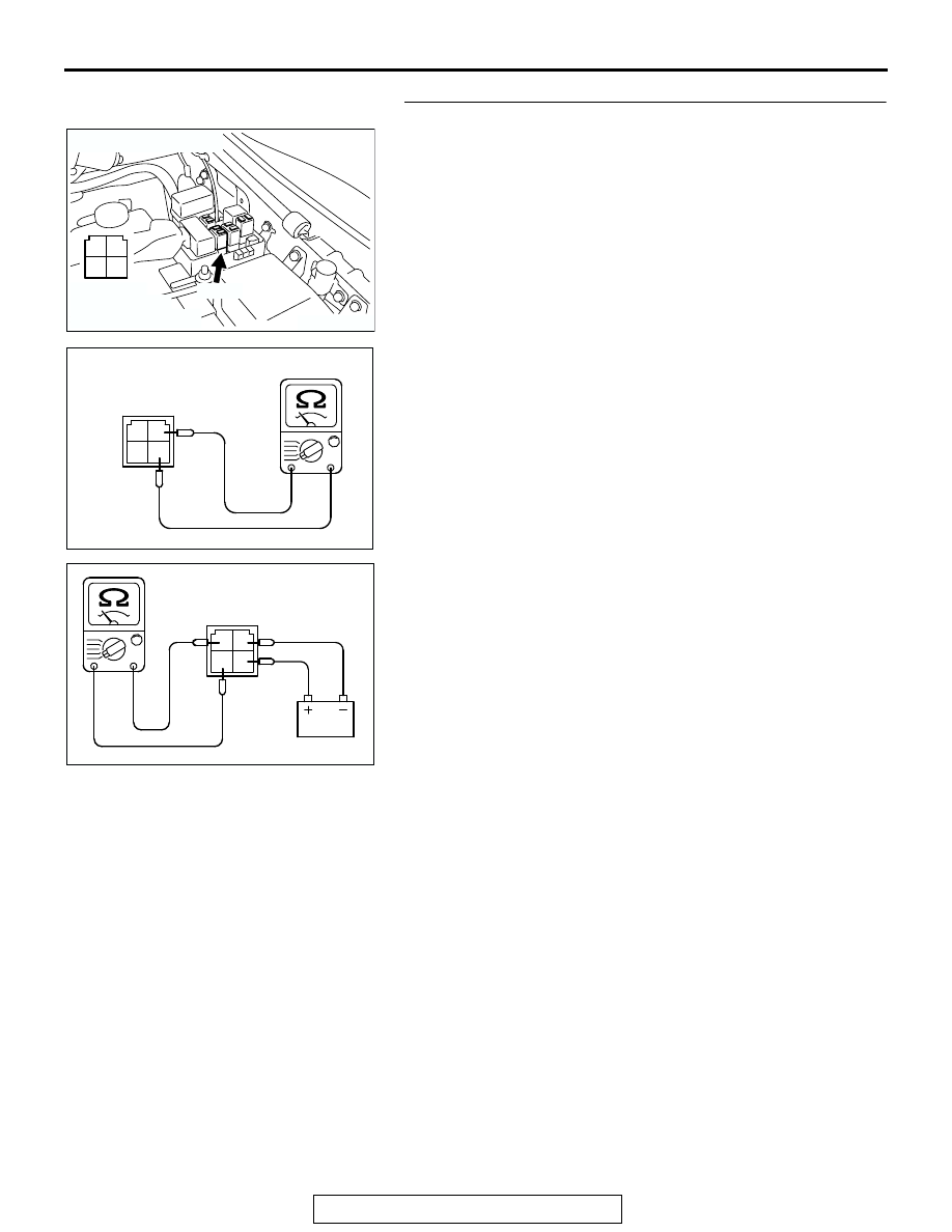
STEP 2. Check the MFI relay.
(1) Remove the MFI relay.

(2) Check for continuity between the MFI relay terminal No. 2 

and No. 4.

• There should be continuity (approximately 70 ohms)

(3) Use jumper wires to connect MFI relay terminal No. 2 to the 

positive battery terminal and terminal No. 4 to the negative 
battery terminal.

(4) Check the continuity between the MFI relay terminal No. 1 

and No. 3 while connecting and disconnecting the jumper 
wire at the negative battery terminal.

• Should be less than 2 ohms. (Negative battery terminal 

connected)

• Should be open loop. (Negative battery terminal discon-

nected)

(5)  Install the MFI relay.
Q: Is the resistance normal?

YES : Go to Step 3.
NO :  Replace the MFI relay. Then confirm that the 

malfunction symptom is eliminated.

AK200951

2 1

3

4

B-22X

AB

CONNECTOR: B-22X

HARNESS 
CONNECTOR: 
COMPONENT SIDE

1

2

3

4

AK201380AE

MFI RELAY SIDE
CONNECTOR

1

2

3

4

AK201381AE

MFI RELAY SIDE
CONNECTOR

MULTIPORT FUEL INJECTION (MFI) DIAGNOSIS

TSB Revision

MULTIPORT FUEL INJECTION (MFI)

13A-912

STEP 3. Measure the power supply voltage at MFI relay 
harness side connector B-22X.
(1) Disconnect the connector B-22X and measure at the 

harness side.

(2) Measure the voltage between terminal No. 2, No. 3 and 

ground.

• Voltage should be battery positive voltage.

Q: Is battery positive voltage (approximately 12 volts) 

present?
YES : 
Go to Step 4.
NO :  Check harness connector A-03 at intermediate 

connector for damage, and repair or replace as 
required. Refer to GROUP 00E, Harness Connector 
Inspection 

P.00E-2

. If intermediate connector A-03 is 

in good condition, repair an open circuit between 
fusible link (5) and MFI relay connector B-22X 
(terminal No. 2, No. 3). Then confirm that the 
malfunction symptom is eliminated.

STEP 4. Check harness connector D-133 at PCM for 
damage.
Q: Is the harness connector in good condition?

YES : Go to Step 5.
NO :  Repair or replace it. Refer to GROUP 00E, Harness 

Connector Inspection 

P.00E-2

. Then confirm that the 

malfunction symptom is eliminated.

AK200951

2 1

3

4

B-22X

AB

CONNECTOR: B-22X

HARNESS 
CONNECTOR: 
COMPONENT SIDE

2 1

3

4

AK201382AE

B-22X HARNESS
CONNECTOR:
COMPONENT SIDE

AK200939

31

32

33

34

35

36

37

38

39

40

41

42

43

44

45

46

47

48

49

52

53

54

55

56

57

58

50

51

AB

CONNECTOR: D-133

HARNESS CONNECTOR: 
COMPONENT SIDE

PCM

D-133(GR)

MULTIPORT FUEL INJECTION (MFI) DIAGNOSIS

TSB Revision

MULTIPORT FUEL INJECTION (MFI)

13A-913

STEP 5. Measure the ignition switch-IG signal voltage at 
PCM harness side connector D-133.
(1) Disconnect the connector D-133 and measure at the 

harness side.

(2) Turn the ignition switch to the "ON" position.

(3) Measure the voltage between terminal No. 50 and ground.

• Voltage should be battery positive voltage.

(4) Turn the ignition switch to the "LOCK" (OFF) position.
Q: Is battery positive voltage (approximately 12 volts) 

present?
YES : 
Go to Step 6.
NO :  Check harness connector E-111, D-02, D-28 at 

intermediate connector for damage, and repair or 
replace as required. Refer to GROUP 00E, Harness 
Connector Inspection 

P.00E-2

. If intermediate 

connector E-111, D-02, D-28 are in good condition, 
repair it because of open circuit between ignition 
switch connector D-204 (terminal No. 2) and PCM 
connector D-133 (terminal No. 50). Then confirm that 
the malfunction symptom is eliminated.

AK200939

31

32

33

34

35

36

37

38

39

40

41

42

43

44

45

46

47

48

49

52

53

54

55

56

57

58

50

51

AB

CONNECTOR: D-133

HARNESS CONNECTOR: 
COMPONENT SIDE

PCM

D-133(GR)

AK201375

31

32

33

34

35

36

37

38

39

40

41

42

43

44

45

46

47

48

49

52

53

54

55

56

57

58

50

51

D-133 HARNESS 
CONNECTOR: 
COMPONENT SIDE

AK201375AB

31

32

33

34

35

36

37

38

39

40

41

42

43

44

45

46

47

48

49

52

53

54

55

56

57

58

50

51

MULTIPORT FUEL INJECTION (MFI) DIAGNOSIS

TSB Revision

MULTIPORT FUEL INJECTION (MFI)

13A-914

STEP 6. Measure the backup power supply voltage at PCM 
harness side connector D-133.
(1) Disconnect the connector D-133 and measure at the 

harness side.

(2) Measure the voltage between terminal No.58 and ground.

• Voltage should be battery positive voltage.

Q: Is battery positive voltage (approximately 12 volts) 

present?
YES : 
Go to Step 7.
NO :  Check harness connector A-03 at intermediate 

connector for damage, and repair or replace as 
required. Refer to GROUP 00E, Harness Connector 
Inspection 

P.00E-2

. If intermediate connector A-03 is 

in good condition, repair an open circuit between 
fusible link (5) and PCM connector D-133 (terminal 
No. 58). Then confirm that the malfunction symptom 
is eliminated.

AK200939

31

32

33

34

35

36

37

38

39

40

41

42

43

44

45

46

47

48

49

52

53

54

55

56

57

58

50

51

AB

CONNECTOR: D-133

HARNESS CONNECTOR: 
COMPONENT SIDE

PCM

D-133(GR)

AK201376

31

32

33

34

35

36

37

38

39

40

41

42

43

44

45

46

47

48

49

52

53

54

55

56

57

58

50

51

D-133 HARNESS 
CONNECTOR: 
COMPONENT SIDE

AK201376AB

31

32

33

34

35

36

37

38

39

40

41

42

43

44

45

46

47

48

49

52

53

54

55

56

57

58

50

51


Content   ..  354  355  356  357   ..