Mitsubishi Montero (2004+). Manual - part 255


  Index      Mitsubishi     Mitsubishi Montero - service repair manual 2004 year


Search            


Content   ..  253  254  255  256   ..


Mitsubishi Montero (2004+). Manual - part 255


MULTIPORT FUEL INJECTION (MFI) DIAGNOSIS

TSB Revision

MULTIPORT FUEL INJECTION (MFI)

13A-507

• MD9919658: Test harness Set

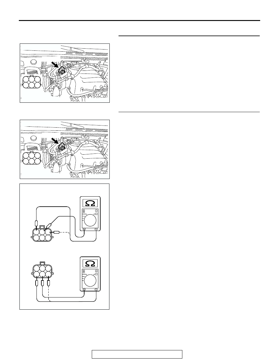
STEP 1. Check connector B-56 at EGR valve for damage.
Q: Is the connector in good condition?

YES : Go to Step 2.
NO :  Repair or replace it. Refer to GROUP 00E, Harness 

Connector Inspection 

P.00E-2

. Then go to Step 12.

STEP 2. Measure the EGR valve motor coil resistance.
(1) Disconnect the EGR valve connector B-56.

(2) Measure the resistance between EGR valve connector 

terminal No. 2 and either terminal No. 1 or terminal No. 3.

Standard value: 20 

 24 ohms [at 20°C (68°F)]

(3) Measure the resistance between EGR valve connector 

terminal No. 5 and either terminal No. 4 or terminal No. 6.

Standard value: 20 

 24 ohms [at 20°C (68°F)]

Q: Is the resistance between 20 and 24 ohms [at 20

°

(68

°F)]?

YES : Go to Step 3.
NO :  Replace the EGR valve. Then go to Step 12.

AK200967

1

2

3

4

5

6

AB

HARNESS 
CONNECTOR: 
COMPONENT SIDE

B-56(GR)

CONNECTOR: B-56

AK200967

1

2

3

4

5

6

AB

HARNESS 
CONNECTOR: 
COMPONENT SIDE

B-56(GR)

CONNECTOR: B-56

1

2 3

4

5 6

1

2 3

4

5 6

AK201418

MULTIPORT FUEL INJECTION (MFI) DIAGNOSIS

TSB Revision

MULTIPORT FUEL INJECTION (MFI)

13A-508

STEP 3. Measure the power supply voltage at EGR valve 
motor harness side connector B-56.
(1) Disconnect the connector B-56 and measure at the harness 

side.

(2) Turn the ignition switch to the "ON" position.

(3) Measure the voltage between terminal No. 2, No. 5 and 

ground.

• Voltage should be battery positive voltage.

(4) Turn the ignition switch to the "LOCK" (OFF) position.
Q: Is battery positive voltage (approximately 12 volts) 

present?
YES : 
Go to Step 5.
NO :  Go to Step 4.

STEP 4. Check connector B-22X at MFI relay for damage.
Q: Is the connector in good condition?

YES : Repair harness wire between MFI relay connector 

B-22X (terminal No. 1) and EGR valve connector 
B-56 (terminal No. 2, No. 5) because of open circuit or 
short circuit to ground. Then go to Step 12.

NO :  Repair or replace it. Refer to GROUP 00E, Harness 

Connector Inspection 

P.00E-2

. Then go to Step 12.

STEP 5. Measure the power supply voltage at PCM 
connector D-132 by backprobing.
(1) Do not disconnect the connector D-132.
(2) Measure the voltage between terminal (No. 3, No. 12, No. 

19, No. 26) and ground by backprobing.

• The voltage should be between 5 and 8 volts for approx-

imately 3 seconds when the ignition switch is turned 
from the "LOCK" (OFF) position to the "ON" position.

(3) Turn the ignition switch to the "LOCK" (OFF) position.
Q: Is the voltage normal?

YES : Go to Step 8.
NO :  Go to Step 6.

AK200967

1

2

3

4

5

6

AB

HARNESS 
CONNECTOR: 
COMPONENT SIDE

B-56(GR)

CONNECTOR: B-56

1

2

3

4

5

6

AK201419

B-56 HARNESS 
CONNECTOR: 
COMPONENT SIDE

AG

AK200951

2 1

3

4

B-22X

AB

CONNECTOR: B-22X

HARNESS 
CONNECTOR: 
COMPONENT SIDE

1

2

3

5

6 7 8 9

4

20

21 22

232425

2627

10111213

14 15

16 1718

19

AK201420

D-132 HARNESS 
CONNECTOR: 
HARNESS SIDE

AB

MULTIPORT FUEL INJECTION (MFI) DIAGNOSIS

TSB Revision

MULTIPORT FUEL INJECTION (MFI)

13A-509

STEP 6. Check connector D-132 at PCM for damage.
Q: Is the connector in good condition?

YES : Go to Step 7.
NO :  Repair or replace it. Refer to GROUP 00E, Harness 

Connector Inspection 

P.00E-2

. Then go to Step 12.

STEP 7. Check for open circuit and short circuit to ground 
between EGR valve connector B-56 and PCM connector 
D-132.

a. EGR valve connector B-56 (terminal No. 1) and PCM con-

nector D-132 (terminal No. 3).

b. EGR valve connector B-56 (terminal No. 3) and PCM con-

nector D-132 (terminal No. 12).

c. EGR valve connector B-56 (terminal No. 4) and PCM con-

nector D-132 (terminal No. 19). 

d. EGR valve connector B-56 (terminal No. 6) and PCM con-

nector D-132 (terminal No. 26).

Q: Is the harness wire in good condition?

YES : Replace the PCM. Then go to Step 12.
NO :  Repair it. Then go to Step 12.

AK200938

2

3

4

5

6

7

8

9

1

10

14

15

16

17

18

19

20

21

22

23

24

25

26

27

11

12

13

AB

CONNECTOR: D-132

HARNESS CONNECTOR: 
COMPONENT SIDE

PCM

D-132(GR)

AK200967

1

2

3

4

5

6

AB

HARNESS 
CONNECTOR: 
COMPONENT SIDE

B-56(GR)

CONNECTOR: B-56

AK200938

2

3

4

5

6

7

8

9

1

10

14

15

16

17

18

19

20

21

22

23

24

25

26

27

11

12

13

AB

CONNECTOR: D-132

HARNESS CONNECTOR: 
COMPONENT SIDE

PCM

D-132(GR)

MULTIPORT FUEL INJECTION (MFI) DIAGNOSIS

TSB Revision

MULTIPORT FUEL INJECTION (MFI)

13A-510

STEP 8. Check connector D-132 at PCM for damage.
Q: Is the connector in good condition?

YES : Go to Step 9.
NO :  Repair or replace it. Refer to GROUP 00E, Harness 

Connector Inspection 

P.00E-2

. Then go to Step 12.

AK200938

2

3

4

5

6

7

8

9

1

10

14

15

16

17

18

19

20

21

22

23

24

25

26

27

11

12

13

AB

CONNECTOR: D-132

HARNESS CONNECTOR: 
COMPONENT SIDE

PCM

D-132(GR)


Content   ..  253  254  255  256   ..