Mitsubishi Montero (2002-2004). Manual - part 962


  Index      Mitsubishi     Mitsubishi Montero - service repair manual 2002-2004 year


Search            


Content   ..  960  961  962  963   ..


Mitsubishi Montero (2002-2004). Manual - part 962


DIAGNOSTIC TROUBLE CODE PROCEDURES <TRANSFER>

TSB Revision

DIAGNOSTIC TROUBLE CODE PROCEDURES

23Ac-331

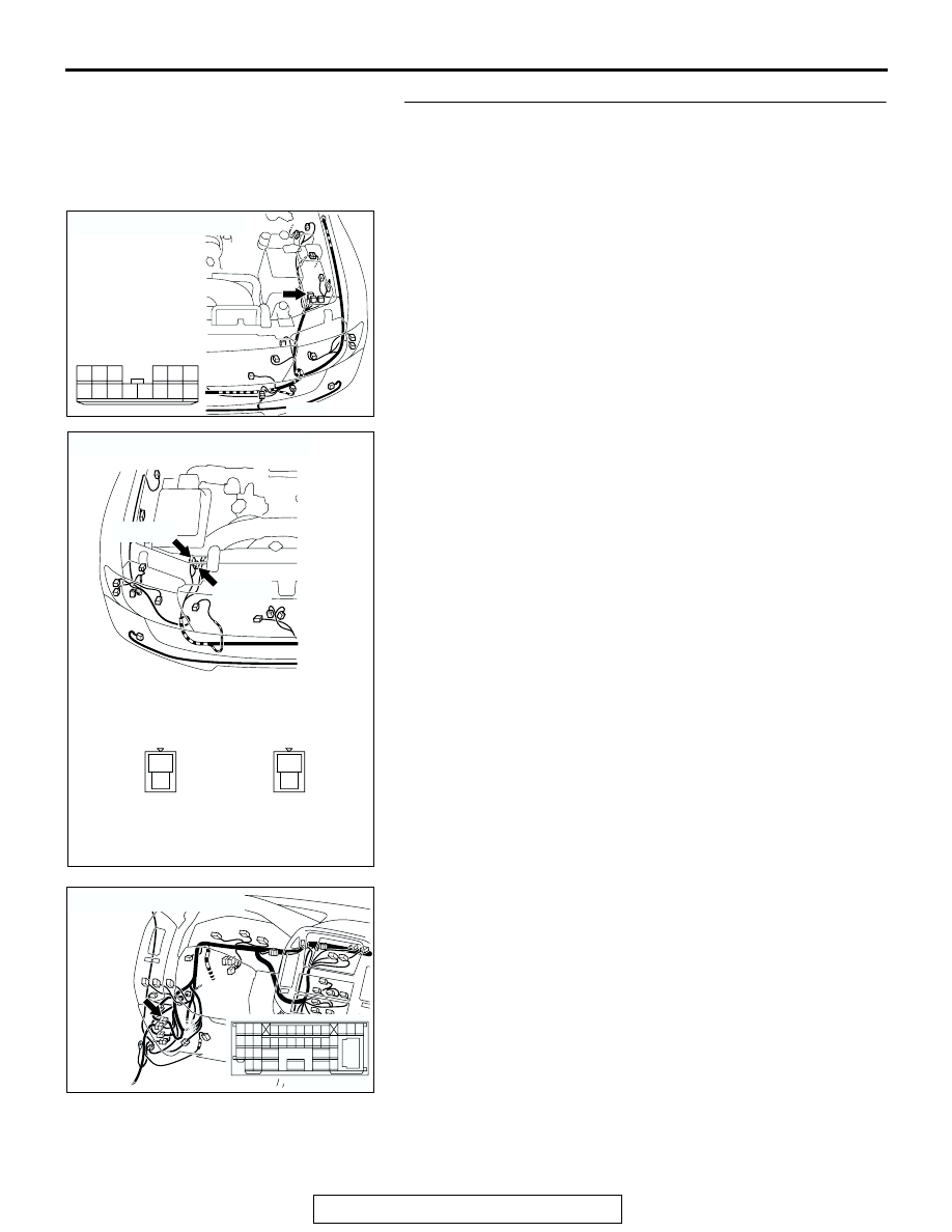
STEP 4. Check joint connector A-15, free-wheel engage 
solenoid valve connectors A-38, A-39, intermediate 
connector D-28, junction block connector D-210 and D-208 
for loose, corroded or damaged terminals, or terminals 
pushed back in the connector.

AC204167

CONNECTOR : A-15

AU

1213

4 5

14

10

3

8 9

2

7

1

6

11

AC204184

CONNECTORS : A-38, A-39

A-38 (B)

A-39 (BR)

AD

A-38

2

1

A-39

2

1

AC204170

CONNECTOR : D-28

CH

2 3

27

32

28

33

16

15

4 5

19

18

29

17

34

7 8

35

22

21

9 10

30

36

31

37

25

24

23

6

20

1

14

26

11

13

12

38

DIAGNOSTIC TROUBLE CODE PROCEDURES <TRANSFER>

TSB Revision

DIAGNOSTIC TROUBLE CODE PROCEDURES

23Ac-332

Q: Are the connectors and terminals in good condition?

YES : Go to Step 5.
NO :  Repair or replace the damaged components. Refer to 

GROUP 00E, Harness Connector Inspection 

P.00E-

2

.

AC204191

CONNECTORS : D-208, D-210

D-208

D-208

D-210

D-210

AP

5 6

2

4

3

1

5

4

12 13

3

2

9

7 8

10

6

1

11

DIAGNOSTIC TROUBLE CODE PROCEDURES <TRANSFER>

TSB Revision

DIAGNOSTIC TROUBLE CODE PROCEDURES

23Ac-333

STEP 5. Check harness for open circuit or short circuit to 
ground between free-wheel engage solenoid valve 
connectors A-38, A-39 terminal 1 and junction block 
connector D-208 terminal 2.
Q: Is the harness wire in good condition?

YES : Go to Step 10.
NO :  Repair or replace the harness wire.

AC204184

CONNECTORS : A-38, A-39

A-38 (B)

A-39 (BR)

AD

A-38

2

1

A-39

2

1

AC204173

CONNECTOR : D-208

BA

5 6

2

4

3

1

JUNCTION BLOCK
(FRONT VIEW)

DIAGNOSTIC TROUBLE CODE PROCEDURES <TRANSFER>

TSB Revision

DIAGNOSTIC TROUBLE CODE PROCEDURES

23Ac-334

STEP 6. Measure the solenoid valve output voltage at the 
transfer-ECU connector E-104 by backprobing.
(1) Do not disconnect connector E-104.
(2) Turn the ignition switch to the "ON" position.
(3) Transmission range should be "N" range.

(4) Measure the voltage between terminal 41 and ground by 

backprobing.

• When the transfer shift lever position is other than 2H, 

voltage should measure battery positive voltage.

• When the transfer shift lever position is 2H, voltage 

should measure less than 1.0 volt.

(5) Turn the ignition switch to the "LOCK" (OFF) position.
Q: Is the measured voltage normal?

YES : Go to Step 9.
NO :  Go to Step 7.

AC204176

CONNECTOR : E-104

BA

51

40

3839

50

41

52

48

37

46

35

47

36

45

34

43

32

44

33

49

42

31

AC204918 BW

E-104 HARNESS CONNECTOR : 
HARNESS SIDE

51

40

3839

50

41

52

48

37

46

35

47

36

45

34

43

32

44

33

49

42

31


Content   ..  960  961  962  963   ..