Mitsubishi Montero (2002-2004). Manual - part 954


  Index      Mitsubishi     Mitsubishi Montero - service repair manual 2002-2004 year


Search            


Content   ..  952  953  954  955   ..


Mitsubishi Montero (2002-2004). Manual - part 954


DIAGNOSTIC TROUBLE CODE PROCEDURES <TRANSFER>

TSB Revision

DIAGNOSTIC TROUBLE CODE PROCEDURES

23Ac-299

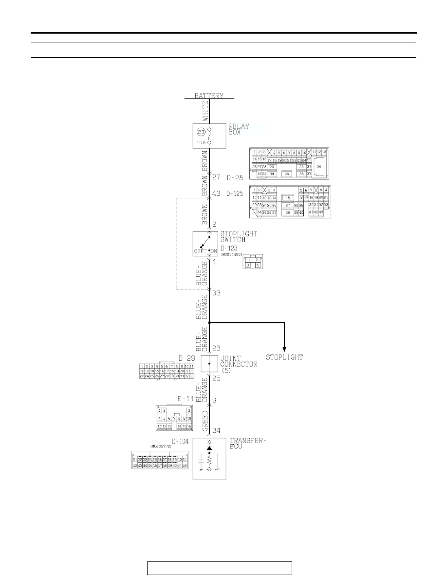
DTC 26: Stoplight Switch System

ACX02034AC

Stoplight Switch System Circuit

DIAGNOSTIC TROUBLE CODE PROCEDURES <TRANSFER>

TSB Revision

DIAGNOSTIC TROUBLE CODE PROCEDURES

23Ac-300

.

CIRCUIT OPERATION

• Battery positive voltage is supplied to the stop-

light switch (terminal 2).

• When the brake pedal is depressed, battery posi-

tive voltage is applied to the transfer-ECU (termi-
nal 34).

.

DTC SET CONDITIONS
In the case that the stoplight switch is continuously 
turned ON for 15 minutes at the vehicle speed of 15 
km/h (9.3 mph) and over, the DTC 26 is set as the 
short circuit of the stoplight switch.

.

TROUBLESHOOTING HINTS (The most likely 
causes for this code to be set are:)

• Malfunction of the stoplight switch circuit

• Damaged harness, connector

• Malfunction of the transfer-ECU

DIAGNOSIS

Required Special Tool:

• MB991502: Scan Tool (MUT-II)

STEP 1. Check the brake pedal height.
Refer to GROUP 35A, On-vehicle Service 

− Brake Pedal 

Check and Adjustment 

P.35A-115

.

Q: Is the height adjusted properly?

YES : Go to Step 2.
NO :  Adjust the brake pedal to the proper height.

AC204188

CONNECTORS : D-28, D-29, D-123, D-125

D-28

D-28

D-29

AZ

D-123

D-123

D-125

D-125

D-29

4

2

3

1

2 3

27

32

28

33

16

15

4 5

19

18

29

17

34

7 8

35

22

21

9 10

30

36

31

37

25

24

23

6

20

1

14

26

11

13

12

38

9

8

6 7

5

3 4

20

32

21

33

43

17 18

30

41

16

29

28

39 40

13

25

12

24

35 36

14

26

37

15

27

38

19

31

42

1

10

22

2

11

23

34

9 10

8

6 7

31 32

30

29

18 19 20 21

5

4

2

1

3

27

26

24

23

25

12 13 14 15 16 17

28

11
22
33

AC204194

CONNECTORS : E-11, E-104

E-104

E-104

E-11

E-11

AV

51

40

3839

50

41

52

48

37

46

35

47

36

45

34

43

32

44

33

49

42

31

3

10

16

9

7 8

6

1

4

2

5

11

14

1213

15

DIAGNOSTIC TROUBLE CODE PROCEDURES <TRANSFER>

TSB Revision

DIAGNOSTIC TROUBLE CODE PROCEDURES

23Ac-301

STEP 2. Using scan tool MB991502, check data list item 23: 
Stoplight Switch.

CAUTION

To prevent damage to scan tool MB991502, always turn the 
ignition switch to the "LOCK" (OFF) position before con-
necting or disconnecting scan tool MB991502.
(1) Connect scan tool MB991502 to the data link connector.
(2) Turn the ignition switch to the "ON" position.
(3) Set scan tool MB991502 to data reading mode for item 23, 

Stoplight Switch 

− Active Trac 4WD II.

• When the brake pedal is depressed, the display on scan 

tool MB991502 should be "ON."

• When the brake pedal is not depressed, the display on 

scan tool MB991502 should be "OFF."

(4) Turn the ignition switch to the "LOCK" (OFF) position.
Q: Is the switch operating properly?

YES : If can be assumed that this malfunction is intermittent. 

Refer to GROUP 00, How to Use Troubleshooting/
Inspection Service Points 

− How to Cope with 

Intermittent Malfunction 

P.00-6

.

NO :  Go to Step 3.

STEP 3. Measure the stoplight switch power supply 
voltage at connector D-123 by backprobing.
(1) Remove the stoplight switch from the mounting bracket.
(2) Do not disconnect connector D-123.

(3) Measure the voltage between terminal 2 and ground by 

backprobing.

• The voltage should measure battery positive voltage.

Q: Is the measured voltage battery positive voltage?

YES : Go to Step 6.
NO :   Go to step 4.

ACX01539AD

MB991502

16-PIN

AC204170

CONNECTOR : D-123

CG

4

2

3

1

AC204918 BB

D-123 HARNESS CONNECTOR : 
HARNESS SIDE

4

2

3

1

DIAGNOSTIC TROUBLE CODE PROCEDURES <TRANSFER>

TSB Revision

DIAGNOSTIC TROUBLE CODE PROCEDURES

23Ac-302

STEP 4. Check stoplight switch connector D-123, 
intermediate connector D-28 and D-125 for loose, corroded 
or damaged terminals, or terminals pushed back in the 
connector.
Q: Are the connectors and terminals in good condition?

YES : Go to Step 5.
NO :  Repair or replace the damaged components. Refer to 

GROUP 00E, Harness Connector Inspection 

P.00E-

2

.

STEP 5. Check the harness for open circuit or short circuit 
to ground between stoplight switch connector D-123 
terminal 2 and the power supply fuse.
Q: Is the harness wire in good condition?

YES : Go to Step 6.
NO :  Repair or replace the harness wire.

AC204188

CONNECTORS : D-28, D-123, D-125

D-28

D-28

AY

D-123

D-123

D-125

D-125

4

2

3

1

2 3

27

32

28

33

16

15

4 5

19

18

29

17

34

7 8

35

22

21

9 10

30

36

31

37

25

24

23

6

20

1

14

26

11

13

12

38

9

8

6 7

5

3 4

20

32

21

33

43

17 18

30

41

16

29

28

39 40

13

25

12

24

35 36

14

26

37

15

27

38

19

31

42

1

10

22

2

11

23

34

AC204170

CONNECTOR : D-123

CG

4

2

3

1


Content   ..  952  953  954  955   ..