Mitsubishi Montero (2002-2004). Manual - part 803


  Index      Mitsubishi     Mitsubishi Montero - service repair manual 2002-2004 year


Search            


Content   ..  801  802  803  804   ..


Mitsubishi Montero (2002-2004). Manual - part 803


SRS AIR BAG DIAGNOSIS

TSB Revision

SUPPLEMENTAL RESTRAINT SYSTEM (SRS) DIAGNOSIS

52Bb-81

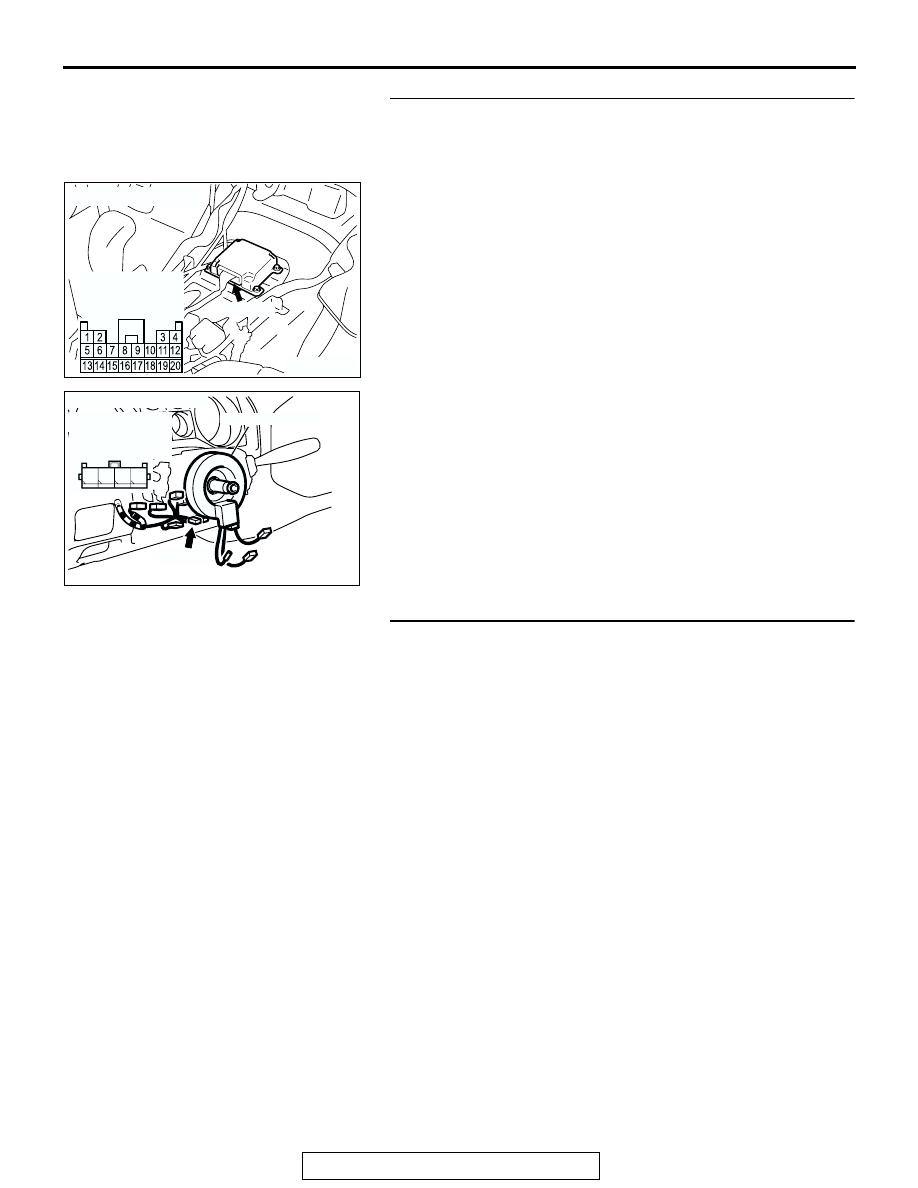
STEP 4. Check the harness for short circuit to power 
supply between SRS-ECU connector E-08 (terminal No.11 
and 12) and clock spring connector D-206 (terminal Noo.3 
and 4).
Q: Are harness wires between the SRS-ECU connector E-

08 (terminal No.11 and 12) and clock spring connector 
D-206 (terminal Noo.3 and 4) in good condition?
YES : 
Go to Step 5.
NO :  Repair the harness wires between SRS-ECU 

connector E-08 and clock spring connector D-206. 
Then go to Step 5.

STEP 5. Recheck for diagnostic trouble code. 
Q: Is DTC 61 set?

YES : Return to Step 1.
NO :  The procedure is complete. (If no malfunctions are not 

found in all steps, an intermittent malfunction is 
suspected. Refer to GROUP 00, How to Use 
Troubleshooting/Inspection Service Points 

− How to 

Cope with Intermittent Malfunction 

P.00-6

.) 

ACX01478AH

CONNECTOR: E-08

E-08 (Y)

HARNESS
CONNECTOR:
HARNESS SIDE

AC204226AC

CONNECTOR: D-206

CLOCK SPRING

D-206 (Y)

HARNESS 
CONNECTOR:
HARNESS SIDE

1 2

4

3

SRS AIR BAG DIAGNOSIS

TSB Revision

SUPPLEMENTAL RESTRAINT SYSTEM (SRS) DIAGNOSIS

52Bb-82

DTC 62: Driver’s Air Bag Module (Squib) System Fault for Ground Circuit (Short-Circuited to ground)

.

AC204430

Driver's Air Bag Module (Squib) Circuit 

NOTE

: CONNECTOR LOCK SWITCH

CONNECTOR

CONNECTED: ON
CONNECTOR

DISCONNECTED: OFF

AB

AC204226AD

CLOCK SPRING

D-206 (Y)

CONNECTORS: D-206, D-229

D-229

ACX01478 AG

CONNECTOR: E-08

E-08 (Y)

SRS AIR BAG DIAGNOSIS

TSB Revision

SUPPLEMENTAL RESTRAINT SYSTEM (SRS) DIAGNOSIS

52Bb-83

CIRCUIT OPERATION

• The SRS-ECU judges how severe a collision is 

by detecting signals from the front impact sensors 
and the front air bag analog G-sensor. If the 
impact is over a predetermined level, the SRS-
ECU outputs an ignition signal. At this time, if the 
front air bag safing G-sensor is on, the SRS air 
bag will inflate. 

• The ignition signal is input to the air bag module 

via the clock spring to inflate the air bag.

.

DTC SET CONDITIONS
This DTC is set if there is abnormal resistance 
between the input terminals of the driver's side air 
bag module (squib). However, if no DTC resets, the 
SRS warning light will be switched off (DTC will be 
retained). 

.

TROUBLESHOOTING HINTS

• Malfunction of the clock spring

• Damaged harness wires and connectors

• Short to the ground in the driver's air bag module 

(squib) harness

• Malfunction of the SRS-ECU

.

DIAGNOSIS

Required Special Tools:

• MB991502: Scan Tool (MUT-II)

• MB991865: Dummy resister

• MB991866: Resister harness

STEP 1. Check the driver's air bag module.
(1) Disconnect the negative battery terminal.
(2) By sliding the A section (in the figure) of air bag module 

connector D-229 in arrow direction, disconnect the 
connector.

(3) Connect special tool MB991865 to special tool MB991866.

CAUTION

Do not insert a test probe into the terminal from its front 
side directly as the connector contact pressure may be 
weakened.
(4) Insert special tool MB991866 into clock spring side air bag 

module connector D-229 by backprobing.

(5) Connect the negative battery terminal.
(6) Erase the diagnostic trouble code memory, and then 

recheck the diagnostic trouble code.

Q:  Is DTC 62 set?

YES : Go to Step 2.
NO :  Replace the driver's air bag module. (Refer to 

P.52Ba-33

.) Then go to Step 5. 

AC100441AE

D-229 AIR BAG MODULE
CONNECTOR

STEERING WHEEL

A

AC006030 AH

D-229 AIR BAG
MODULE
CONNECTOR

MB991865
(DUMMY RESISTOR : 3

Ω)

MB991866 (RESISTOR 
HARNESS)

SRS AIR BAG DIAGNOSIS

TSB Revision

SUPPLEMENTAL RESTRAINT SYSTEM (SRS) DIAGNOSIS

52Bb-84

STEP 2. Check the clock spring.
(1) Disconnect the negative battery terminal.
(2) Disconnect the clock spring connector D-206.
(3) Connect special tool MB991865 to special tool MB991866.

CAUTION

Do not insert a test probe into the terminal from its front 
side directly as the connector contact pressure may be 
weakened.
(4) Insert special tool MB991866 into clock spring harness side 

connector D-206 (terminal No.3 and 4) by backprobing.

(5) Connect the negative battery terminal.
(6) Erase the diagnostic trouble code memory, and check the 

diagnostic trouble code.

Q: Is DTC 62 set?

YES : Go to Step 3.
NO :  Replace the clock spring. (Refer to 

P.52Bb-85

.) Then 

go to Step 5. 

AC006031

D-206 CLOCK SPRING
CONNECTOR

AJ

MB991865
(DUMMY RESISTOR : 3

Ω)

MB991866 (RESISTOR 
HARNESS)

1 2

4

3

(REAR VIEW)


Content   ..  801  802  803  804   ..