Mitsubishi Montero (2002-2004). Manual - part 740
TSB Revision
SYMPTOM PROCEDURES
13Ad-9
.
CIRCUIT OPERATION
• The malfunction indicator lamp (service engine
soon or check engine lamp) power is supplied
from the ignition switch.
• The PCM controls the ground of the malfunction
indicator lamp (service engine soon or check
engine lamp) by turning the power transistor in
the PCM ON and OFF.
.
COMMENT
• The PCM causes the malfunction indicator lamp
(service engine soon or check engine lamp) to
illuminate for 20 seconds immediately after the
ignition switch is turned to the "ON" position
occurred.
.
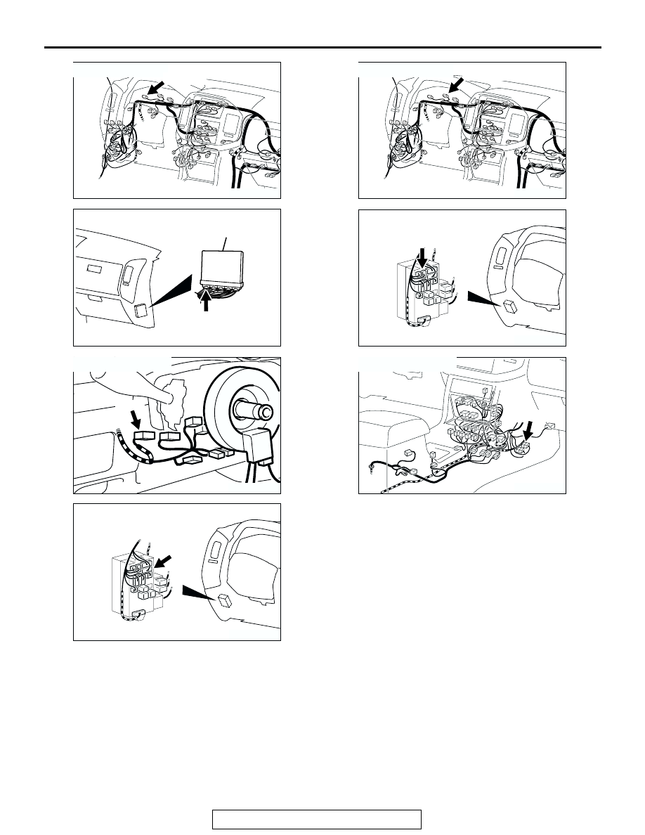
AK201042AD
D-03(GR)
CONNECTOR: D-03
AK201038
CONNECTOR: D-132
AB
PCM
D-132(GR)
AK201045
D-204
AB
CONNECTOR: D-204
AK201041AC
CONNECTOR: D-210
D-210
AK201042AE
CONNECTOR: D-04
D-04(GR)
AK201041AD
CONNECTOR: D-208
D-208
AK201043
E-111
AB
CONNECTOR: E-111