Mitsubishi Montero (2002-2004). Manual - part 204
SPECIAL TOOLS
TSB Revision
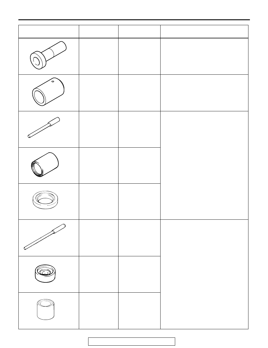
FRONT AXLE
26-13
MD999547 Oil
seal installer
−
Removal of front differential mount
insulator <Front side, Rear side (LH)>
MD999570
Crankshaft front
oil seal insulator
−
Removal of front differential mount
insulator <Rear side (RH)>
MB990947
Lower arm
bushing arbor
MB990947
Press fitting of front differential mount
insulator <Front side, Rear side (LH)>
MB990847 Rear
suspension
bushing remover
and installer
base
MB990847
MB990981
Mount bushing
remover and
installer
−
MB991318
Lower arm
bushing arbor
−
Press fitting of front differential mount
insulator <Rear side (RH)>
MB991183
Bushing arbor
−
MB990843
Draglink bushing
remover and
installer
−
TOOLS
TOOL NUMBER
AND NAME
SUPERSESSION APPLICATION
MB990947
MB990847
MB990981
MB991318
MB991183
MB990843