Mitsubishi Montero (1998+). Manual - part 36
than 0.5 volt or more than 4.5 volts, or an open or short
circuit in "G" sensor system.
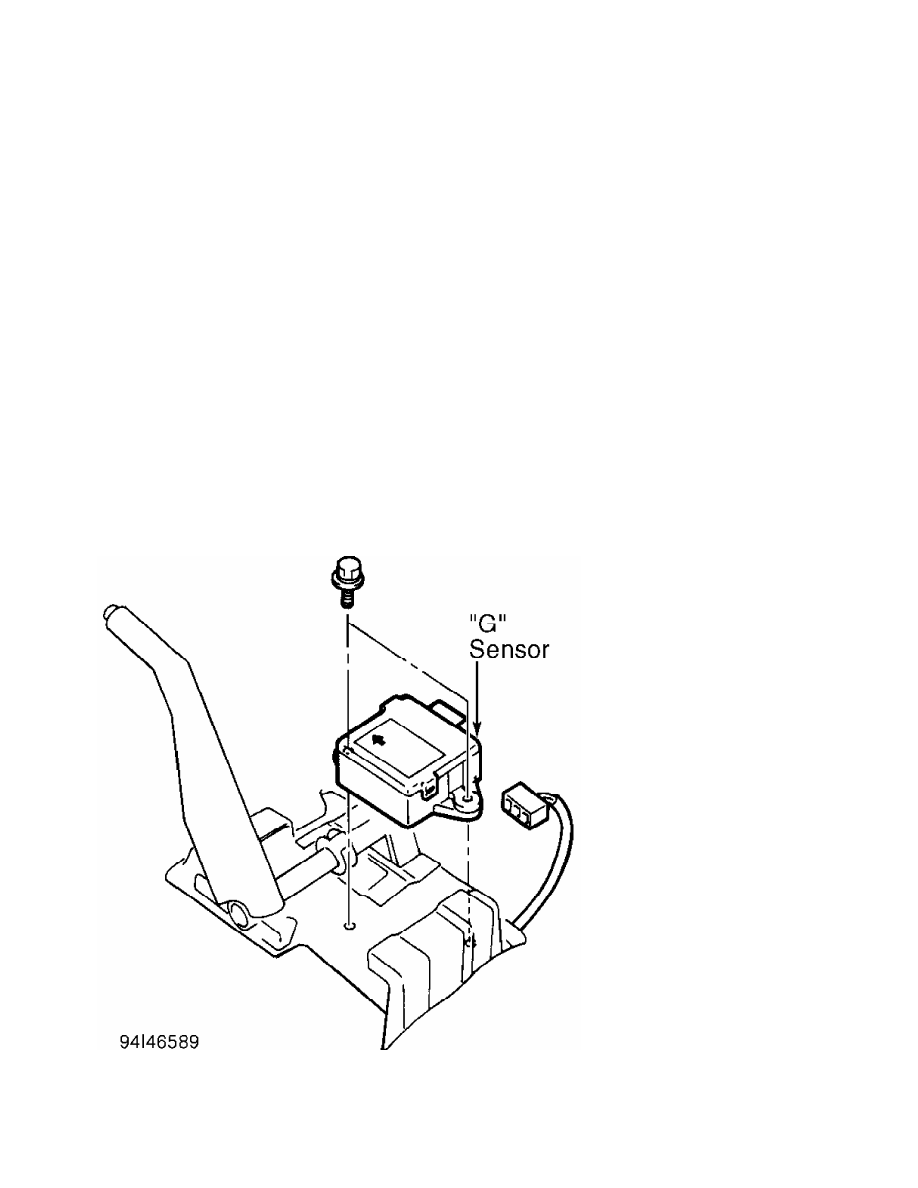
1) Disconnect "G" sensor connector. Sensor is located on
bracket under center console, next to shifter. See Fig. 10. Connect
Special Tool (MB991348) between sensor and connector. Using a DVOM,
check voltage between sensor connector terminals No. 2 (Blue/White
wire) and No. 3 (Black/Red wire). Voltage should be 2.38-2.62 volts.
If voltage is as specified, reconnect sensor connector and go to step
3). If voltage is not as specified, leave special tool and DVOM
connected and go to next step.
2) Note top center position of sensor, and remove sensor. See
"G" SENSOR under REMOVAL & INSTALLATION. Secure sensor so that arrow
on sensor is facing straight down. Voltage should be 3.4-3.6 volts. If
voltage is specified, reinstall sensor and go to next step. If voltage
is not as specified, replace sensor.
3) Turn ignition off. Disconnect ECU 26-pin connector. Turn
ignition on. Check voltage between ECU 26-pin connector terminals No.
4 and 17. See Figs. 5-6. Voltage should be 2.4-2.6 volts. If voltage
is as specified, go to next step. If voltage is not as specified,
check and repair connectors and related wiring harness between ECU and
sensor. See WIRING DIAGRAMS.
4) Check and repair ECU 26-pin connector. If connector is
okay, replace ECU.
Fig. 10: Locating "G" Sensor
Courtesy of Mitsubishi Motor Sales of America.
DTC 33: STOPLIGHT SWITCH SYSTEM