Mitsubishi Montero (1991+). Manual - part 3


  Index      Mitsubishi     Mitsubishi Montero - service repair manual 1991 year


Search            


Content   ..  1  2  3  4  ..


Mitsubishi Montero (1991+). Manual - part 3


surfaces. Resurface head if warpage exceeds specification. See

CYLINDER HEAD (SOHC) table under ENGINE SPECIFICATIONS at end of

article. Replace cylinder head if it is not within specification after

resurfacing.

         Installation (SOHC)

         1) Ensure mating surfaces are clean and dry. Note

identification mark located on front of head gasket. Identification

marks are: "R" for SOHC, "2DN" for DOHC non-turbocharged and "2DT" for

DOHC turbocharged engine. Install head gasket with identification mark

toward timing belt side of engine and facing upward. Ensure all holes

are aligned.

NOTE:    Install head gasket with identification mark toward timing

         belt side of engine and facing upward. Ensure all holes

         align. Install washers on head bolts with chamfered side

         toward bolt head.

         2) Install cylinder head and bolts. Ensure washers are

installed on head bolts with chamfered side toward bolt head. Using

proper sequence, tighten bolts to specification in 2-3 steps. See

Fig. 5. See appropriate TORQUE SPECIFICATIONS table at end of article.

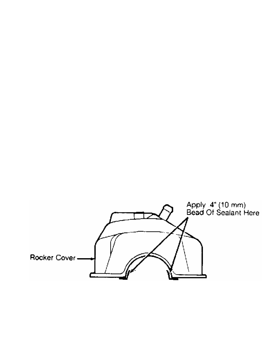
         3) Apply sealant to rocker cover sealing surfaces before

installation. See Fig. 6. Ensure rocker cover gasket projections are

aligned with notches in rocker cover. Coat all "O" rings with oil, and

install a new "O" ring on distributor adapter and oil dipstick tube.

         4) Coat camshaft area with oil prior to installing

distributor adapter. To complete installation, reverse removal

procedure. Tighten bolts and nuts to specification. See appropriate

TORQUE SPECIFICATIONS table. After engine reaches normal operating

temperature, allow engine to cool, and retighten cylinder head bolts.

Fig. 6:  Applying Sealant to Rocker Cover (SOHC)

Courtesy of Mitsubishi Motor Sales of America, Inc.

         Removal (DOHC)

         1) Drain cooling system. Remove upper and lower intake

manifolds and brackets. See UPPER INTAKE MANIFOLD and LOWER INTAKE

MANIFOLD under REMOVAL & INSTALLATION.

         2) Remove turbocharger(s) (if equipped). See TURBOCHARGER

under REMOVAL & INSTALLATION. Remove heat shields from exhaust

manifolds. Remove exhaust manifolds. See EXHAUST MANIFOLDS under

REMOVAL & INSTALLATION.

         3) Remove spark plug wires and ignition coils. Remove rocker

cover and gasket. Remove timing belt and timing belt inner covers. See

TIMING BELT under REMOVAL & INSTALLATION. Remove intake camshaft

sprockets.

         4) Remove coolant manifold and coolant inlet pipe. Using

Socket (MD998051), remove cylinder head bolts. Remove cylinder head

and camshaft assemblies. Note direction of washer installation on head

bolts.

         Inspection (DOHC)

         Check cylinder head height. Check warpage at gasket and

manifold surfaces. Resurface head if warpage exceeds specification.

See CYLINDER HEAD (DOHC) table under ENGINE SPECIFICATIONS at end of

article. After resurfacing, recheck cylinder head height. Replace

cylinder head if it is not within specification.

         Installation (DOHC)

         1) Ensure mating surfaces are clean and dry. Note

identification mark located on front of head gasket. Identification

marks are: "R" for SOHC, "2DN" for DOHC non-turbocharged and "2DT" for

DOHC turbocharged engine. Install head gasket with identification mark

toward timing belt side of engine and facing upward. Ensure all holes

are aligned.

NOTE:    Install head gasket with identification mark toward timing

         belt side of engine and facing upward. Ensure all holes

         align. Install washers on head bolts with chamfered side

         toward bolt head.

         2) Install cylinder head and bolts. Ensure washers are

installed on head bolts with chamfered side toward bolt head. Using

proper sequence, tighten bolts to specification in 2-3 steps. See

Fig. 5. See TORQUE SPECIFICATIONS (3000GT) table at end of article. On

turbocharger equipped engines, back off head bolts once, and repeat

tightening procedure.

         3) To reinstall camshaft sprocket, hold hexagonal area of

camshaft using wrench while tightening sprocket bolt. Tighten rocker

cover bolts in a crisscross pattern. Start at 4 corners of rocker

cover and move toward center.

NOTE:    Rocker cover bolts are color coded. Front cylinder bank

         bolts are black; rear cylinder bank bolts are green.

         4) To complete installation, reverse removal procedure.

Tighten bolts and nuts to specification. See TORQUE SPECIFICATIONS

(3000GT) table.

         FRONT CRANKSHAFT OIL SEAL

         Removal & Installation

         Remove timing belt and crankshaft sprocket. See TIMING BELT

under REMOVAL & INSTALLATION. Pry oil seal from oil pump. To install,

coat seal lip with grease. Using Seal Installer (MD998717), install

seal in oil pump. Install remaining components. See appropriate TORQUE

SPECIFICATIONS table at end of article.

         TIMING BELT

         Removal (Montero & Pickup)

         1) Drain cooling system. Disconnect upper radiator hose.

Remove upper radiator shroud. Remove cooling fan and fan clutch

assembly. Remove cooling fan pulley. Remove all drive belts. Remove

power steering pump with pressure and return hoses connected, and set

aside.

         2) Remove power steering pump brackets. Remove A/C tensioner

pulley and mounting bracket. Remove A/C compressor with hoses

connected, and remove mounting bracket. Remove cooling fan bracket

assembly. Note location and length of bolts for reassembly reference.

         3) Remove No. 1 and No. 2 timing belt upper outer covers and

gaskets. See Fig. 7. Remove timing belt lower outer cover and gaskets.

Using Holder (MB998747) and a used "V" belt, remove crankshaft pulley

bolt. Remove crankshaft pulley.

NOTE:    "V" belt will be damaged by tool. DO NOT use engine "V"

         belt to hold crankshaft pulley unless replacing belt.

         4) Remove flange. See Fig. 7. Rotate crankshaft and align all

timing marks. See Fig. 8. Loosen belt tensioner bolt, and rotate belt

tensioner counterclockwise to release belt tension.

         5) If reusing timing belt, place arrow on belt to indicate

direction of belt rotation. Remove timing belt and belt tensioner. If

camshaft sprocket requires removal, install Holder (MB990775) on

camshaft sprocket. Remove retaining bolt and camshaft sprocket. Remove

rear timing belt cover (if required).

Fig. 7:  Exploded View of Timing Belt Components (SOHC Is Similar)

Courtesy of Mitsubishi Motor Sales of America, Inc.

Fig. 8:  Aligning Timing Marks (SOHC)

Courtesy of Mitsubishi Motor Sales of America, Inc.

         Inspection (Montero & Pickup)

         Inspect timing belt for wear on edges of drive teeth. Inspect

belt for oil contamination, cracks, separation, worn or missing teeth

and hardened back surface. Replace belt if worn, damaged or

contaminated. Inspect belt tensioner for smooth rotation. Replace if

defective.

         Installation (Montero & Pickup)

         1) Install rear timing belt cover. Tighten bolts to

specification. See TORQUE SPECIFICATIONS (MONTERO & PICKUP) table at

end of article. Install camshaft sprockets (if removed). Using holder,

hold camshaft and tighten retaining bolt to specification.

         2) Install belt tensioner and spring. Ensure spring is

secured on pin of water pump and engaged in hole of belt tensioner

with hook of spring pointing from cylinder block.

         3) Rotate belt tensioner counterclockwise as much as

possible, and temporarily tighten bolt. Align all timing marks with

No. 1 cylinder at TDC of compression stroke. See  Fig. 8.

         4) Install timing belt on crankshaft sprocket and then left

camshaft sprocket with all slack removed from tension side of belt.

Route timing belt onto water pump pulley, right camshaft sprocket and

tensioner. Remove any slack from belt by rotating left and then right

camshaft sprockets counterclockwise.

         5) Ensure belt is installed in original direction of rotation

and all timing marks are aligned. Install flange on crankshaft. Loosen

belt tensioner bolts slightly, and allow tensioner to apply belt

tension.

         6) Using Crankshaft Socket (MD998716), rotate crankshaft 2


Content   ..  1  2  3  4  ..