Mitsubishi Galant (2004+). Manual - part 780


  Index      Mitsubishi     Mitsubishi Galant - service repair manual 2004 year


Search            


Content   ..  778  779  780  781   ..


Mitsubishi Galant (2004+). Manual - part 780


MANUAL A/C DIAGNOSIS

TSB Revision

HEATER, AIR CONDITIONING AND VENTILATION

55A-259

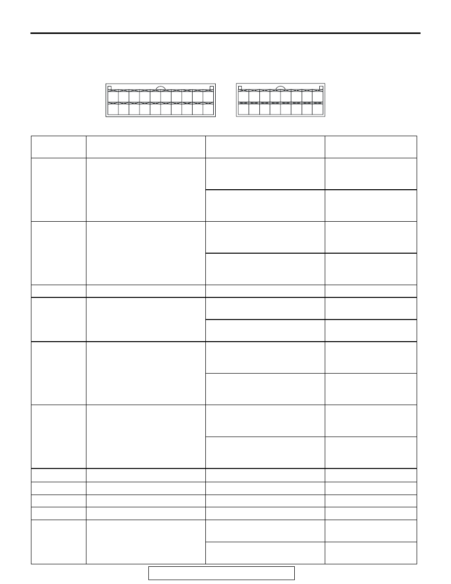
CHECK AT A/C-ECU TERMINAL <MIDDLE TYPE>

M1552010300583

8

2

1

5

3 4

6 7

9 10

20

19

18

17

16

15

14

13

12

11

32

24

29

21

31

30

2223

27

35

33

25

34

26

36

28

AC210339

C-15

C-16

AB

TERMINAL 
NO.

CHECK ITEM

CHECKING REQUIREMENTS NORMAL CONDITION

1

Air mixing damper control motor When the air mix damper is 

moved to the MAX. COOL 
position. 

10 V

When the air mix damper is 
moved to the MAX. HOT 
position. 

0.5 V

2

Air mixing damper control motor When the air mix damper is 

moved to the MAX. COOL 
position. 

0.5 V

When the air mix damper is 
moved to the MAX. HOT 
position. 

10 V

3

Back-up power supply

Always

Battery positive voltage

4

Mode selection damper control 
motor (DEF)

When the damper is moved to 
the FACE position. 

0.5 V

When the damper is moved to 
the DEF position. 

10 V

5

Outside/inside air selection 
damper control motor (outside)

When the damper flap is 
moving to the air recirculation 
position.

0.5 V

When the damper flap is 
moving to the outside air 
position.

0 V (when the motor is 
stopped)

6

Outside/inside air selection 
damper control motor (inside)

When the damper flap is 
moving to the air recirculation 
position.

0 V (when the motor is 
stopped)

When the damper flap is 
moving to the outside air 
position.

0.5 V

7

8

Rear window defogger relay

Ignition switch: ON

Battery positive voltage

9

Blower relay

Ignition switch: ON

Battery positive voltage

10

A/C compressor relay

A/C compressor relay: ON

Battery positive voltage

11

Mode selection damper control 
motor (FACE)

When the damper is moved to 
the FACE position. 

10 V

When the damper is moved to 
the DEF position. 

0.5 V

MANUAL A/C DIAGNOSIS

TSB Revision

HEATER, AIR CONDITIONING AND VENTILATION

55A-260

12

A/C pressure sensor

Ignition switch: ON

5 V

13 

− 15

16

Potentiometer power supply

Ignition switch: ON

5 V

17

Power transistor (BASE)

When the blower speed 
selection dial shows Maximum 
air volume.

1 V

18

Power transistor 
(COLLECTOR)

When the blower speed 
selection dial shows Maximum 
air volume.

7.5 V

19

20

Sensors and potentiometers 
ground

Always

0 V

21

Mode selection damper control 
motor potentiometer input

When the damper has moved to 
the DEF position. 

0.7 

− 1.3 V

22

23

Ambient air temperature sensor 
input

When sensor temperature is 
25

°C (77°F) [4 kΩ]

1.9 V

24

25

Air thermo sensor input

When sensor temperature is 
25

°C (77°F) [1.5 kΩ]

2.2 V

26

A/C pressure sensor

at 2.6 MPa

3.9 V

27

Ground

Always

0 V

28

Power supply to the ignition 
switch (IG2)

Ignition switch: ON

Battery positive voltage

29

Air mixing damper control motor 
potentiometer input

When the damper door has 
moved to the MAX. HOT 
position. 

0.7 

− 1.3 V

30

Illumination ground

Always

0 V

31

ILL power supply

Lighting switch: ON

Battery positive voltage

32, 33

34

A/C pressure sensor ground

Always

0 V

36

Power supply to the ignition 
switch (ACC)

Ignition switch: ON

Battery positive voltage

TERMINAL 
NO.

CHECK ITEM

CHECKING REQUIREMENTS NORMAL CONDITION

SPECIAL TOOLS

TSB Revision

HEATER, AIR CONDITIONING AND VENTILATION

55A-261

SPECIAL TOOLS

M1552000600334

TOOL

TOOL NUMBER 
AND NAME

SUPERSESSION

APPLICATION

MB991367 
Special spanner

MB991367-01

Armature mounting nut of 
compressor removal and 
installation

MB991386 Pin

MIT217213

Armature mounting nut of 
compressor removal and 
installation

MB991658
Test harness set

Tool not available

Inspection of throttle position 
sensor

B991367

MB991658

SPECIAL TOOLS

TSB Revision

HEATER, AIR CONDITIONING AND VENTILATION

55A-262

MB991958
A: MB991824
B: MB991827
C: MB991910
D: MB991911
E: MB991914
F: MB991825
G: MB991826
MUT-III Sub 
Assembly
A: Vehicle 
Communication 
Interface (V.C.I)
B: MUT-III USB 
Cable
C: MUT-III Main 
Harness A 
(Vehicles with 
CAN 
communication 
system)
D: MUT-III Main 
Harness B 
(Vehicles without 
CAN 
communication 
system)
E: MUT-III Main 
Harness C (for 
Chrysler models 
only)
F: MUT-III 
Adapter Harness
G: MUT-III 
Trigger Harness

MB991824-KIT
NOTE: G: MB991826 
MUT-III Trigger 
Harness is not 
necessary when 
pushing V.C.I. 
ENTER key.

Checking diagnostic trouble codes

CAUTION

For vehicles with CAN 
communication, use MUT-III 
main harness A to send 
simulated vehicle speed. If you 
connect MUT-III main harness B 
instead, the CAN 
communication does not 
function correctly.

TOOL

TOOL NUMBER 
AND NAME

SUPERSESSION

APPLICATION

MB991910

MB991826

MB991958

MB991911

MB991914

MB991824

MB991827

MB991825

DO NOT USE

A

B

C

D

E

F

G

DO NOT USE


Content   ..  778  779  780  781   ..