Mitsubishi Galant (2004+). Manual - part 773


  Index      Mitsubishi     Mitsubishi Galant - service repair manual 2004 year


Search            


Content   ..  771  772  773  774   ..


Mitsubishi Galant (2004+). Manual - part 773


MANUAL A/C DIAGNOSIS

TSB Revision

HEATER, AIR CONDITIONING AND VENTILATION

55A-231

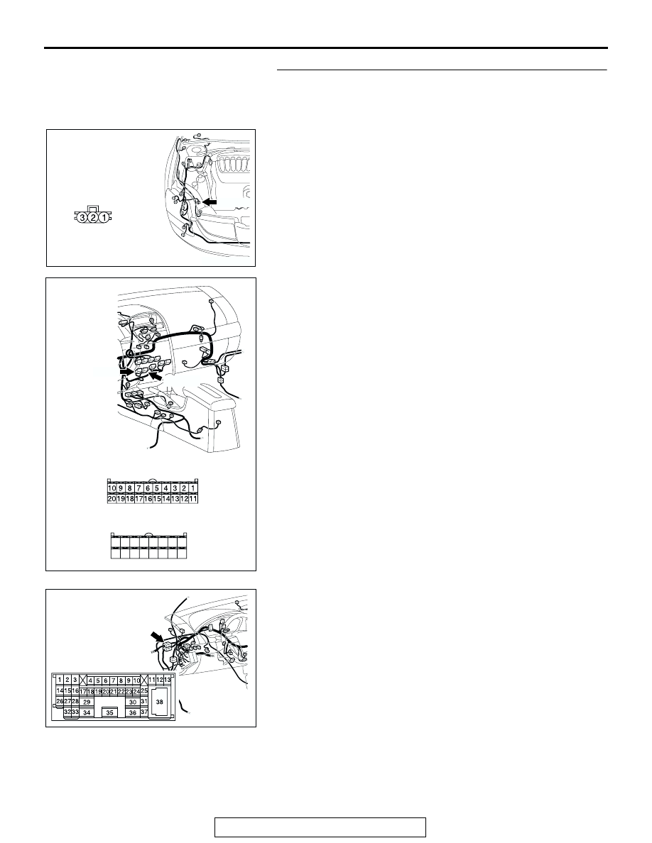
STEP 6. Check the wiring harness between A/C-ECU 
connector C-15 (terminal 12), C-16 (terminals 34 and 26) 
and A/C pressure sensor connector A-30 (terminals 3, 1 
and 2).

NOTE: Also check intermediate connector C-29 for loose, cor-
roded, or damaged terminals, or terminals pushed back in the 
connector. If intermediate connector C-29 is damaged, repair or 
replace the connector as described in GROUP 00E, Harness 
Connector Inspection 

P.00E-2

.

Q: Is the wiring harness between A/C-ECU connector C-15 

(terminal 12), C-16 (terminals 34 and 26) and A/C 
pressure sensor connector A-30 (terminals 3, 1 and 2) in 
good condition?
YES : 
Repair the A/C-ECU. Check that the air conditioning 

works normally. 

NO :  Repair the wiring harness. Check that the air 

conditioning works normally. 

AC305206

CONNECTOR: A-30

AY

HARNESS SIDE

A-30 (B)

AC305234

CONNECTORS: C-15, C-16

C-16 (B)

HARNESS SIDE

C-16

C-15

C-15 (B)

HARNESS SIDE

21

22

23

24

25

26

27

28

29

30

31

32

33

34

35

36

AG

AC305231AI

CONNECTOR: C-29

MANUAL A/C DIAGNOSIS

TSB Revision

HEATER, AIR CONDITIONING AND VENTILATION

55A-232

STEP 7. Check the refrigerant level.

Use the refrigerant recovery station to remove all of the refrig-
erant, and then calculate the amount of the refrigerant and 
charge it.
Q: Is the refrigerant level correct?

YES : Replace the A/C-ECU.Check that the air conditioning 

works normally. 

NO :  Correct the refrigerant level (Refer to On-vehicle 

Service

P.55A-266

). Check that the air conditioning 

works normally. 

MANUAL A/C DIAGNOSIS

TSB Revision

HEATER, AIR CONDITIONING AND VENTILATION

55A-233

INSPECTION PROCEDURE 8: Defogger Function Does Not Operate.

IGNITION
SWITCH (IG2)

1

FUSIBLE 
LINK

DEFOGGER
RELAY

CHOKE
COIL

JUNCTION
BLOCK

DEFOGGER

A/C-
ECU

Defogger Circuit

MANUAL A/C DIAGNOSIS

TSB Revision

HEATER, AIR CONDITIONING AND VENTILATION

55A-234

.

TECHNICAL DESCRIPTION (COMMENT)
If the defogger does not operate when the defogger 
switch is turned on, the defogger relay system may 
be defective.

.

TROUBLESHOOTING HINTS

• Malfunction of the A/C-ECU

• Malfunction of the defogger relay

• Damaged harness wires or connectors

DIAGNOSIS

Required Special Tool:

• MB991223: Test Harness Set

STEP 1. Check the A/C and outside/inside air selection 
damper control motor operation.
Q: Do the A/C and outside/inside air selection damper 

control motor work normally?
YES : 
Go to Step 2.
NO :  Refer to Inspection procedure 10, "Malfunction of the 

A/C-ECU power supply system

P.55A-246

."

STEP 2. Check defogger relay connector C-201 for loose, 
corroded or damaged terminals, or terminals pushed back 
in the connector.

Q: Is defogger relay connector C-201 in good condition?

YES : Go to Step 3.
NO :  Repair or replace the connector. Refer to GROUP 

00E, Harness Connector Inspection 

P.00E-2

. The 

defogger system should work normally.

AC305233

C-15 (B)

BI

CONNECTOR: C-15

AC305415

JUNCTION BLOCK 
(FRONT VIEW) 

C-204

C-211

C-215

C-201

C-216 (B)

BF

CONNECTORS: C-201, C-204, C-211
C-215, C-216

AC305231CH

CONNECTOR: C-29

AC305268

CONNECTORS: D-08, D-11, D-13, D-14

D-08

D-11

D-13

D-14

AO

AC305415BE

CONNECTOR: C-201

JUNCTION BLOCK SIDE

JUNCTION BLOCK 
(FRONT VIEW)


Content   ..  771  772  773  774   ..