Mitsubishi Galant (2004+). Manual - part 717
 

  Index      Mitsubishi     Mitsubishi Galant - service repair manual 2004 year


Search            


Content   ..  715  716  717  718   ..


Mitsubishi Galant (2004+). Manual - part 717


MANUAL A/C DIAGNOSIS

TSB Revision

HEATER, AIR CONDITIONING AND VENTILATION

55A-7

CAUTION

To prevent damage to scan tool MB991958, always turn the 
ignition switch to the "LOCK" (OFF) position before con-
necting or disconnecting scan tool MB991958.
NOTE: If the battery voltage is low, diagnostic trouble codes will 
not be output. Check the battery if scan tool MB991958 does 
not display.
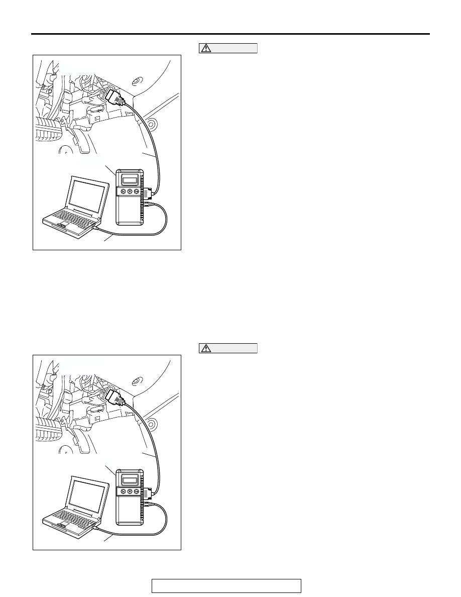
1. Connect the scan tool MB991958 to the data link connector.
2. Turn the ignition switch to the "ON" position.
3. Select "Interactive Diagnosis" from the start-up screen.
4. Select "System Select."
5. Choose "Air Conditioner" from the "BODY" tab.
6. Select "MITSUBISHI."
7. Select "Diagnostic Trouble Code."
8. If a DTC is set, it is shown.
9. Choose "Erase DTC" to erase the DTC.

HOW TO READ DATA LIST

Required Special Tool:

•  MB991958: Scan Tool (MUT-III Sub Assembly)

• MB991824: Vehicle Communication Interface (V.C.I.)

• MB991827: MUT-III USB Cable

• MB991910: MUT-III Main Harness A (Vehicles with CAN 

communication system)

CAUTION

To prevent damage to scan tool MB991958, always turn the 
ignition switch to the "LOCK" (OFF) position before con-
necting or disconnecting scan tool MB991958.
1. Connect the scan tool MB991958 to the data link connector.
2. Turn the ignition switch to the "ON" position.
3. Select "Interactive Diagnosis" from the start-up screen.
4. Select "System Select."
5. Choose "Air Conditioner" from the "BODY" tab.
6. Select "MITSUBISHI."
7. Select "Data List."
8. Choose an appropriate item and select the "OK" button.

AC305412

AB

MB991910

DATA LINK

CONNECTOR

MB991824

MB991827

AC305412

AB

MB991910

DATA LINK

CONNECTOR

MB991824

MB991827

MANUAL A/C DIAGNOSIS

TSB Revision

HEATER, AIR CONDITIONING AND VENTILATION

55A-8

HOW TO PERFORM ACTUATOR TEST

Required Special Tool:

•  MB991958: Scan Tool (MUT-III Sub Assembly)

• MB991824: Vehicle Communication Interface (V.C.I.)

• MB991827: MUT-III USB Cable

• MB991910: MUT-III Main Harness A (Vehicles with CAN 

communication system)

CAUTION

To prevent damage to scan tool MB991958, always turn the 
ignition switch to the "LOCK" (OFF) position before con-
necting or disconnecting scan tool MB991958.
1. Connect the scan tool MB991958 to the data link connector.
2. Turn the ignition switch to the "ON" position.
3. Select "Interactive Diagnosis" from the start-up screen.
4. Select "System Select."
5. Choose "Air Conditioner" from the "BODY" tab.
6. Select "MITSUBISHI."
7. Choose "Actuator Test" from "AUTO A/C" screen.
8. Choose an appropriate item and select the "OK" button.

HOW TO DIAGNOSE THE CAN BUS LINE

Required Special Tool:

•  MB991958: Scan Tool (MUT-III Sub Assembly)

• MB991824: Vehicle Communication Interface (V.C.I.)

• MB991827: MUT-III USB Cable

• MB991910: MUT-III Main Harness A (Vehicles with CAN 

communication system)

AC305412

AB

MB991910

DATA LINK

CONNECTOR

MB991824

MB991827

MANUAL A/C DIAGNOSIS

TSB Revision

HEATER, AIR CONDITIONING AND VENTILATION

55A-9

CAUTION

To prevent damage to scan tool MB991958, always turn the 
ignition switch to the "LOCK" (OFF) position before con-
necting or disconnecting scan tool MB991958.
1. Connect scan tool MB991958 to the data link connector.
2. Turn the ignition switch to the "ON" position.
3. Select "CAN bus diagnosis" from the start-up screen.
4. When the vehicle information is displayed, confirm that it 

matches the vehicle whose CAN bus lines will be 
diagnosed.

• If they matches, go to step 8.

• If not, go to step 5.

5. Select "view vehicle information" button.
6. When the vehicle information is displayed, confirm again 

that it matches the vehicle which is diagnosed CAN bus line.

• If they match, go to step 8.

• If not, go to step 5.

7. Press the "OK" button.
8. When the options are displayed, choose the options (mark 

the check) and then select "OK".

AC305412

AB

MB991910

DATA LINK

CONNECTOR

MB991824

MB991827

MANUAL A/C DIAGNOSIS

TSB Revision

HEATER, AIR CONDITIONING AND VENTILATION

55A-10

DIAGNOSTIC TROUBLE CODE CHART <LOW TYPE>

M1554004900203

CAUTION

During diagnosis, a DTC code associated with 
other system may be set when the ignition switch 
is turned on with connector(s) disconnected. On 
completion of repairs, confirm all systems for 
DTC code(s). If DTC code(s) are set, erase them 
all.

DIAGNOSTIC 
TROUBLE CODE 
NO.

DIAGNOSTIC ITEM

REFERENCE 
PAGE

B1011

Ambient air temperature sensor system (short circuit)

P.55A-11

B1012

Ambient air temperature sensor system (open circuit)

P.55A-11

B1021

Air thermo sensor system (short circuit)

P.55A-18

B1022

Air thermo sensor system (open circuit)

P.55A-18

B1041

Air mixing damper control motor and potentiometer (potentiometer 
system shorted to its power supply)

P.55A-23

B1042

Air mixing damper control motor and potentiometer (potentiometer 
system shorted to its ground)

P.55A-23

B1045

Air mixing damper control motor and potentiometer (activating 
system failure)

P.55A-29

B1061

Mode selection damper control motor and potentiometer 
(potentiometer system shorted to its power supply)

P.55A-35

B1062

Mode selection damper control motor and potentiometer 
(potentiometer system shorted to its ground)

P.55A-35

B1065

Mode selection damper control motor and potentiometer (activating 
system failure)

P.55A-41

U1073

Bus off

P.55A-46

U1100

Powertrain control module time-out (related to engine)

P.55A-48

U1111

Multi-center display unit (middle grade type) time-out

P.55A-52

U1120

Failure information on powertrain control module (related to engine)

P.55A-55


Content   ..  715  716  717  718   ..