Mitsubishi Galant (2004+). Manual - part 591


  Index      Mitsubishi     Mitsubishi Galant - service repair manual 2004 year


Search            


Content   ..  589  590  591  592   ..


Mitsubishi Galant (2004+). Manual - part 591


PISTON AND CONNECTING ROD

TSB Revision

ENGINE OVERHAUL <2.4L ENGINE>

11B-53

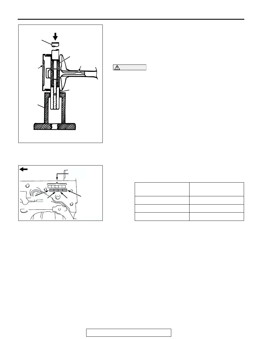
3. Insert the press pin through the piston pin hole. Select the 

correct connecting rod guide pin (See above). Thread the 
guide pin onto the threaded portion of the press pin.

4. Position the piston assembly on the piston support in the 

press. With the press pin up as shown, insert the guide pin 
through the hole in the piston and through the hole in the 
piston support.

CAUTION

To avoid piston damage, the piston support must seat 
squarely against the piston. Verify that the piston pin will 
slide through the hole in the piston support.
5. Press the piston pin out of the assembly.
6. Remove the piston pin from the press pin.

INSTALLATION SERVICE POINTS

.

>>A<< PISTON PIN INSTALLATION
1. When replacing the piston, read off the cylinder bore size 

mark on the cylinder block as illustrated, and select a piston 
according to the following table.

NOTE: The piston size mark shows on the top of the piston.

AK301793

PRESS
PIN

PISTON PIN

FRONT MARK

FRONT
MARK

CONNECTING
ROD GUIDE PIN

BASE

AB

CYLINDER BORE SIZE 
MARK

PISTON SIZE MARK

I

A

II

None

III

C

AK301530

No.4

No.3

No.1

No.2

TIMING BELT SIDE

AC

CRANKSHAFT 
BORE SIZE MARK

PISTON AND CONNECTING ROD

TSB Revision

ENGINE OVERHAUL <2.4L ENGINE>

11B-54

2. Thread the stop screw and lock nut assembly into the base. 

Fit the correct piston support on top of the base. Insert the 
press pin, threaded end up, into the hole in the piston 
support until the press pin touches the stop screw.

3. Using the markings on the press pin, adjust the stop screw 

to the depth shown on the instruction for special tool 
MIT216941.

4. Place the base on press support blocks.
5. Slide the piston pin over the threaded end of the press pin, 

and thread the correct guide pin up against it.

6. Coat the piston pin with engine oil. With the connecting rod 

held in position, slide the guide pin through the piston and 
connecting rod.

7. Press the piston pin through the connecting rod until the 

guide pin contacts the stop screw.

CAUTION

Due to production tolerance variations, it is necessary to 
visually inspect the piston pin depth after installation to 
verify that the piston pin is centered. Adjust if necessary.
8. Remove the piston assembly from the base. Remove the 

guide pin and press pin from the assembly.

AK301794

PRESS
PIN

BASE

PISTON
SUPPORT

LOCKNUT

STOP SCREW

FLAT PISTON 
SUPPORT

PIN DEPTH SET 
LOCATION

AB

AK301795

PRESS
PIN

PISTON PIN

FRONT MARK

FRONT
MARK

CONNECTING
ROD GUIDE PIN

BASE

AB

JAM NUT

STOP
SCREW

PISTON AND CONNECTING ROD

TSB Revision

ENGINE OVERHAUL <2.4L ENGINE>

11B-55

9. Check that the piston moves smoothly.

.

>>B<< OIL RING INSTALLATION
1. Fit the oil ring spacer into the piston ring groove.

CAUTION

Do not use a piston ring expander when installing the side 
rail.
2. Install the upper side rail.

To install the side rail, first fit one end of the rail into the 
piston groove, then press the remaining portion into position 
by hand. See illustration.
NOTE: The side rails and spacer may be installed in either 
direction.
NOTE: New spacers and side rails are colored for identifica-
tion of their sizes.

3. Install the lower side rail in the same manner as described in 

step 2.

4. Make sure that the side rails move smoothly in both 

directions.

.

>>C<< PISTON RING NUMBER 2/PISTON RING NUMBER 1 
INSTALLATION
1. Using the piston ring expander, fit number 2 into the number 

2 groove of piston.
NOTE: Install piston rings with identification mark facing up, 
to the piston crown side.

2. Install the number 1 piston ring in the same manner as step 

1.

AK301796

SIZE

IDENTIFICATION 
COLOR

Standard

None

0.50 mm (0.020 in) 
oversize diameter

Red

AK300190

SIDE RAIL END

AC

AK300395AD

UPPER
SIDE RAIL

SPACER

LOWER 
SIDE RAIL

AK300191

PISTON RING
EXPANDER

AC

PISTON AND CONNECTING ROD

TSB Revision

ENGINE OVERHAUL <2.4L ENGINE>

11B-56

Identification mark:

Number 1 ring: None
Number 2 ring: 2R

NOTE: Confirm the profile for No.1 and No.2 piston rings 
carefully. Install them correctly by paying careful attention to 
the direction of the top and bottom.
NOTE: The identification mark and the size mark are 
stamped on the upper plane of the piston ring (piston top 
side).

3. To prevent incorrect installation, check the identification 

mark of each piston ring. The identification mark is stamped 
near the ring gap.

.

>>D<< CONNECTING ROD BEARING INSTALLATION
1. Measure the crankshaft pin diameter and confirm its 

classification from the following table. On a crankshaft 
supplied as a service part, identification marks of its pins are 
stamped at the positions shown in the illustration.

2. If the crankshaft pin outside diameter identification mark is 

"I," for example, select a bearing whose identification mark 
is "1."
If there is no identification color paint on the crankshaft, 
measure the pin outside diameter and select a bearing 
appropriate for the measured value.

3. Install the selected bearing in the big end and in the cap of 

the connecting rod.

.

SIZE

SIZE MARK

Standard

None

0.50 mm (0.020 in) 
oversize diameter

50

AK301452AC

No.1

No.2

CRANKSHAFT PIN OUTSIDE 
DIAMETER

CONNECTING 
ROD BEARING

IDENTIFICAT
ION MARK

SIZE mm (in)

IDENTIFICATI
ON MARK

I

44.995 

− 45.000 

(1.7715 

− 1.7717)

1

II

44.985 

− 44.995 

(1.7711 

− 1.7715)

2

III

44.980 

− 44.985 

(1.7709 

− 1.7711)

3

AK202909

No. 3

No. 1

No. 2

No. 4

AD

IDENTIFICATION MARK OF CRANKSHAFT
PIN DIAMETER

AK300397

IDENTIFICATION
MARK POSITION

AE


Content   ..  589  590  591  592   ..