Mitsubishi Galant (2004+). Manual - part 261
SYMPTOM PROCEDURES
TSB Revision
SIMPLIFIED WIRING SYSTEM (SWS)
54B-235
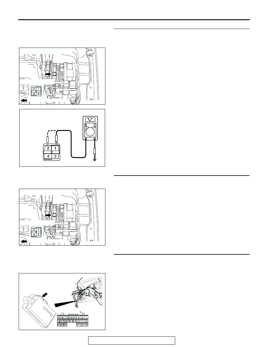
STEP 10. Check the battery power supply circuit to the
horn relay. Measure the voltage at horn relay connector
A-06X.
(1) Disconnect horn relay connector A-06X and measure the
voltage available at the relay box side of the connector.
(2) Measure the voltage between terminal 1 and ground, and
also between terminal 2 and ground.
• The voltage should measure approximately 12 volts
(battery positive voltage).
Q: Is the measured voltage approximately 12 volts (battery
positive voltage)?
YES : Go to Step 12.
NO : Go to Step 11.
STEP 11. Check the wiring harness between horn relay
connector A-06X (terminals 1 and 2) and the battery.
Q: Is the wiring harness between horn relay connector
A-06X (terminals 1 and 2) and the battery in good
condition?
YES : No action is necessary and testing is complete.
NO : The wiring harness may be damaged or the
connector(s) may have loose, corroded or damaged
terminals, or terminals pushed back in the connector.
Repair the wiring harness as necessary. Verify that
the horn sounds normally.
STEP 12. Check ETACS-ECU connector C-217 for loose,
corroded or damaged terminals, or terminals pushed back
in the connector.
Q: Is ETACS-ECU connector C-217 in good condition?
YES : Go to Step 13.
NO : Repair or replace the damaged component(s). Refer
to GROUP 00E, Harness Connector Inspection
. Verify that the horn sounds normally.
AC305992
RELAY BOX SIDE
CONNECTOR: A-06X
AC
FRONT OF VEHICLE
AC209365EL
CONNECTOR A-06X
(RELAY BOX SIDE)
AC305992
RELAY BOX SIDE
CONNECTOR: A-06X
AC
FRONT OF VEHICLE
AC305413
C-217
CONNECTOR: C-217
AE
HARNESS SIDE
JUNCTION BLOCK
(REAR VIEW)