Mitsubishi Galant (2004+). Manual - part 205
SWS DIAGNOSIS
TSB Revision
SIMPLIFIED WIRING SYSTEM (SWS)
54B-11
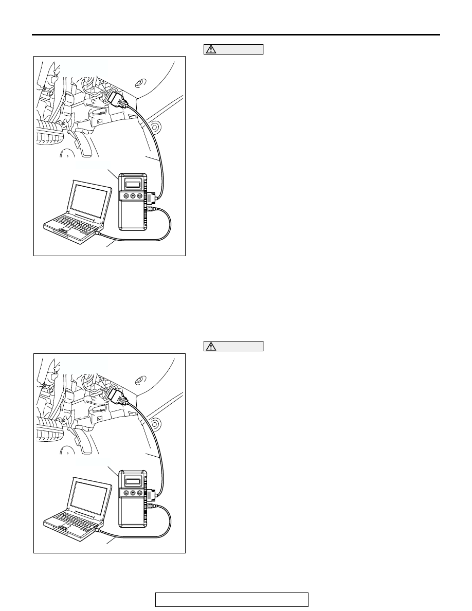
CAUTION
To prevent damage to scan tool MB991958, always turn the
ignition switch to the "LOCK" (OFF) position before con-
necting or disconnecting scan tool MB991958.
NOTE: If the battery voltage is low, diagnostic trouble codes will
not be set. Check the battery if scan tool MB991958 does not
display.
1. Connect scan tool MB991958 to the data link connector.
2. Turn the ignition switch to the "ON" position.
3. Select "Interactive Diagnosis" from the start-up screen.
4. Select "System select."
5. Choose "ETACS" from the "BODY" tab.
6. Select "Diagnostic Trouble Code."
7. If a DTC is set, it is shown.
8. Choose "Erase DTCs" to erase the DTC.
HOW TO DIAGNOSE THE CAN BUS LINES
Required Special Tools:
• MB991958: Scan Tool (MUT-III Sub Assembly)
• MB991824: Vehicle Communication Interface (V.C.I.)
• MB991827: MUT-III USB Cable
• MB991910: MUT-III Main Harness A
CAUTION
To prevent damage to scan tool MB991958, always turn the
ignition switch to the "LOCK" (OFF) position before con-
necting or disconnecting scan tool MB991958.
1. Connect scan tool MB991958 to the data link connector.
2. Turn the ignition switch to the "ON" position.
3. Select "CAN bus diagnosis" from the start-up screen.
4. When the vehicle information is displayed, confirm that it
matches the vehicle being diagnosed.
• If they match, go to step 8.
• If not, go to step 5.
5. Select the "view vehicle information" button.
6. Enter the vehicle information and select the "OK" button.
7. When the vehicle information is displayed, confirm again
that it matches the vehicle being diagnosed.
• If they match, go to step 8.
• If not, go to step 5.
8. Select the "OK" button.
9. When the optional equipment screen is displayed, choose
the one which the vehicle is fitted with, and then select the
"OK" button.
AC305412
AB
MB991910
DATA LINK
CONNECTOR
MB991824
MB991827
AC305412
AB
MB991910
DATA LINK
CONNECTOR
MB991824
MB991827