Mitsubishi Galant (2004+). Manual - part 161


  Index      Mitsubishi     Mitsubishi Galant - service repair manual 2004 year


Search            


Content   ..  159  160  161  162   ..


Mitsubishi Galant (2004+). Manual - part 161


TIMING BELT

TSB Revision

ENGINE MECHANICAL <3.8L ENGINE>

11C-51

CAUTION

Do not remove the setting pin from the auto-tensioner.

(4) Install the auto-tensioner to the engine.

.

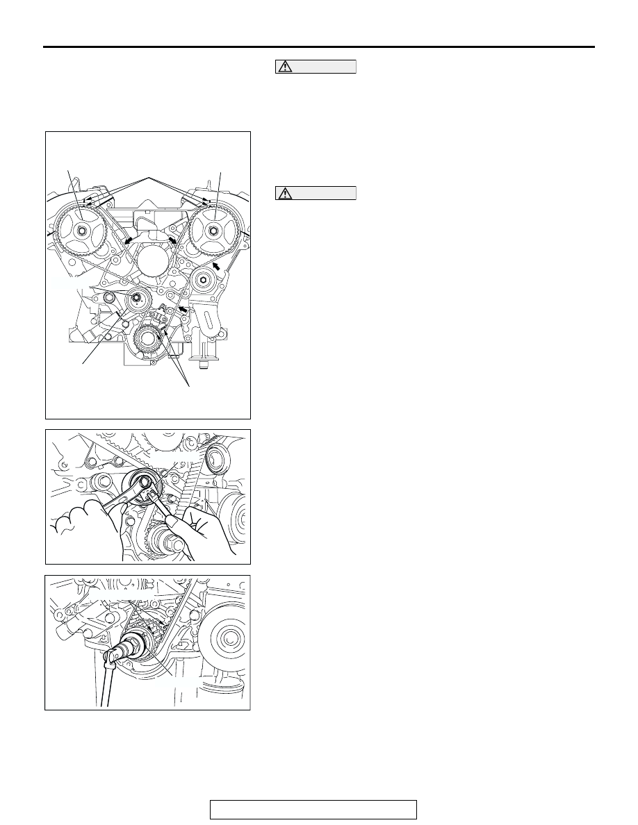
>>B<< TIMING BELT INSTALLATION
1. Align the timing marks on the camshaft sprockets with those 

on the rocker cover and the timing mark on the crankshaft 
sprocket with that on the engine block as shown in the 
illustration.

CAUTION

The camshaft sprocket (right bank) can turn easily due to 
the spring force applied, so be careful not to get your fin-
gers caught.
2. Install the timing belt by the following procedure so that 

there is no deflection in the timing belt between each 
sprocket and pulley.

(1) Crankshaft sprocket
(2) Idler pulley
(3) Camshaft sprocket (Left bank)
(4) Water pump pulley
(5) Camshaft sprocket (Right bank)
(6) Tensioner pulley

3. Turn the camshaft sprocket (Right bank) counterclockwise 

until the tension side of the timing belt is firmly stretched. 
Check all the timing marks again.

4. Use special tool MD998767 to push the tensioner pulley into 

the timing belt, then temporarily tighten the center bolt.

5. Use special tool MD998769 to turn the crankshaft 1/4 turn 

counterclockwise, then turn it again clockwise until the 
timing marks are aligned.

AC206490

TIMING MARK

TIMING MARK

CENTER 
BOLT

TENSION
PULLEY

CAMSHAFT
SPROCKET
(LEFT BANK)

CAMSHAFT
SPROCKET
(RIGHT BANK)

AC

AC205274AB

MD998767

AC205275

MD998769

TIMING MARK

AB

TIMING BELT

TSB Revision

ENGINE MECHANICAL <3.8L ENGINE>

11C-52

CAUTION

When tightening the center bolt, be careful that the ten-
sioner pulley does not turn with the bolt.
6. Loosen the center bolt of the tensioner pulley. Use special 

tool MD998767 and a torque wrench to apply the tension 
torque to the timing belt as shown in the illustration. Then 
tighten the center bolt to the specified torque.

Standard value: 4.4 N

m (39 in-lb) <Timing belt ten-

sion torque>

Tightening torque: 48 

± 6 Nm (36 ± 4 ft-lb)

7. Remove the setting pin that has been inserted into the 

auto-tensioner.

8. Turn the crankshaft clockwise twice to align the timing 

marks.

9. Wait for at least five minutes, then check that the 

auto-tensioner pushrod extends within the standard value 
range.

Standard value (A): 4.8 

 6.0 mm (0.19  0.24 inch)

10.If not, repeat the operation in steps 1 to 8 above.
11.Check again that the timing marks of the sprockets are 

aligned.

.

>>C<< CRANKSHAFT PULLEY INSTALLATION
Use special tools MB991800 and MB991802 to install the 
crankshaft pulley.

AC206418

MD998767

TENSIO-
NER
PULLEY

4.4 N·m
39 in-lb

48 ± 6 N·m
36 ± 4 ft-lb

AB

AC205276

SETTING PIN

AB

AC206419

AB

A

ACX01675AB

MB991800

MB991802

TIMING BELT

TSB Revision

ENGINE MECHANICAL <3.8L ENGINE>

11C-53

INSPECTION

M1112004400437

AUTO-TENSIONER ADJUSTER CHECK

1. Check for oil leak from seal, and replace it if leak is detected.
2. Check for wear or damage at the top of the rod. Replace it, if 

required.

3. While holding the auto-tensioner with your hand, press the 

end of the pushrod against a metal surface (such as the 
cylinder block) with a force of 98 

− 196 N (22 − 44 pound) 

and measure how far the pushrod is pushed in.

Standard value: Within 1 mm (0.04 inch)
A: Length when no force is applied
B: Length when force is applied

 B: Movement in

4. If the measured value is out of the standard value, replace 

the auto-tensioner adjuster.

ACX00536

AUTO-TENSIONER

SPRING

PUSHROD

AB

AC206608AB

A

B

AUTO-
TENSIONER

ROD

MOVEMENT

98 – 196 N
(22 – 44 lb)

CYLINDER BLOCK HEATER UNIT

TSB Revision

ENGINE MECHANICAL <3.8L ENGINE>

11C-54

CYLINDER BLOCK HEATER UNIT

REMOVAL AND INSTALLATION

M1112006900029

Pre-removal Operation
• Front No.1 Exhaust Pipe Removal (Refer to GROUP 15, 

Exhaust Pipe and Main Muffler 

P.15-21

).

• Front No.2 Exhaust Pipe Removal (Refer to GROUP 15, 

Exhaust Pipe and Main Muffler 

P.15-21

).

Post-installation Operation
• Front No.2 Exhaust Pipe Installation (Refer to GROUP 15, 

Exhaust Pipe and Main Muffle

P.15-21

).

• Front No.1 Exhaust Pipe Installation (Refer to GROUP 15, 

Exhaust Pipe and Main Muffle

P.15-21

).

AC306622

1

2

2.6 ± 0.2 N·m
23 ± 2 in-lb

AB

22 ± 4 N·m
16 ± 3 ft-lb

41 ± 8 N·m
30 ± 6 ft-lb

3

N

REMOVAL STEPS

1.

CYLINDER BLOCK HEATER 
COVER

2.

CYLINDER BLOCK HEATER UNIT 
CONNECTOR

<<A>>

>>A<<

3.

CYLINDER BLOCK HEATER UNIT 

REMOVAL STEPS (Continued)


Content   ..  159  160  161  162   ..