Mitsubishi Galant (2004+). Manual - part 1586


  Index      Mitsubishi     Mitsubishi Galant - service repair manual 2004 year


Search            


Content   ..  1584  1585  1586  1587   ..


Mitsubishi Galant (2004+). Manual - part 1586


SRS AIR BAG DIAGNOSIS

TSB Revision

SUPPLEMENTAL RESTRAINT SYSTEM (SRS)

52B-237

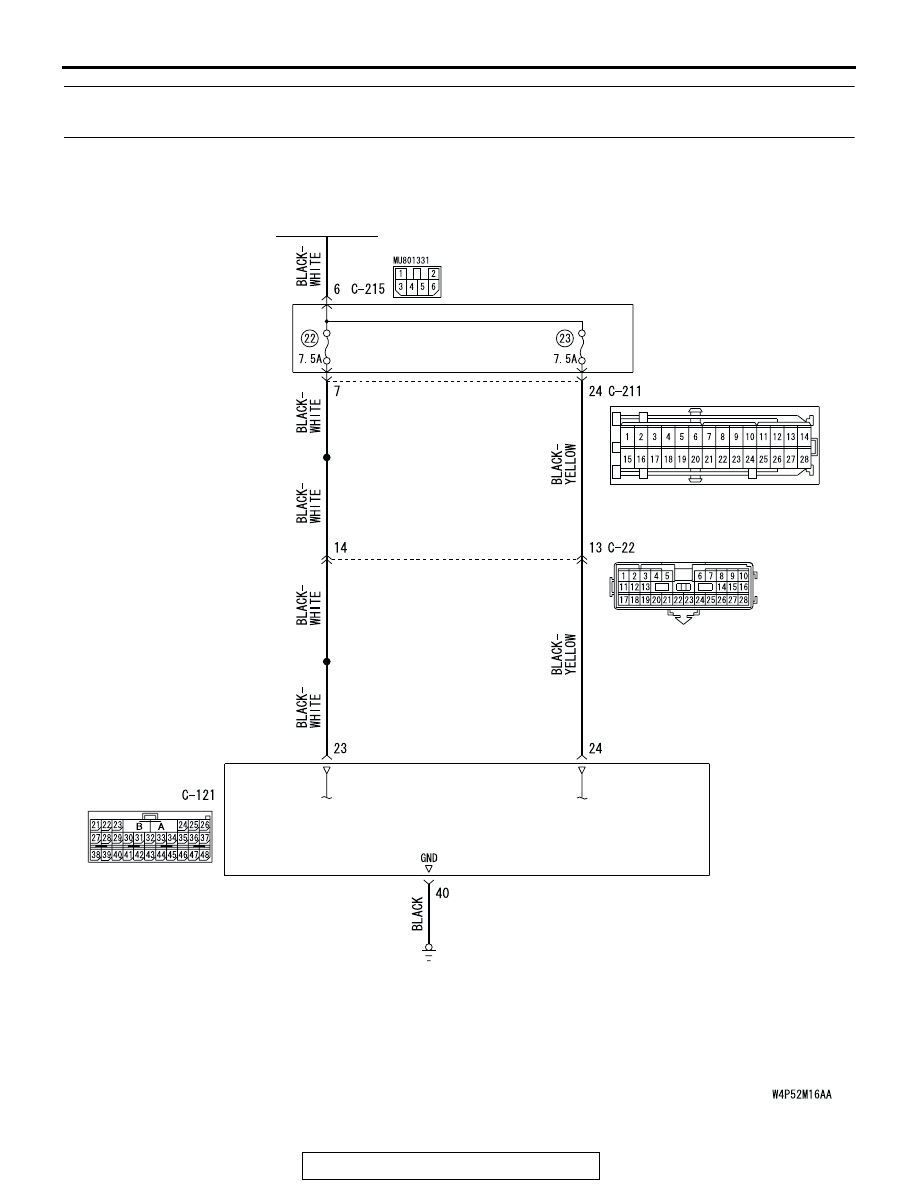
DTC B1476: IG1 Power Supply Circuit System (Fuse No.22 Circuit) DTC B1477: IG1 Power Supply 
Circuit System (Fuse No.23 Circuit)

IGNITION
SWITCH (IG1)

JUNCTION
BLOCK

SRS-ECU

IG1 Power Supply Circuit

SRS AIR BAG DIAGNOSIS

TSB Revision

SUPPLEMENTAL RESTRAINT SYSTEM (SRS)

52B-238

CAUTION

If DTC B1476 <Fuse No.22> or B1477 <Fuse 
No.23> is set in the combination meter, always 
diagnose the CAN bus lines.

.

CIRCUIT OPERATION

• The SRS-ECU is powered from the ignition 

switch (IG1).

• The SRS-ECU power is supplied from two cir-

cuits. Even if one circuit is shut off, the air bag 
can inflate.

.

DTC SET CONDITIONS
This DTC is set if the voltage between the IG1 termi-
nals (fuse No.22 circuit or fuse No.23 circuit) and 
ground is lower than a predetermined value for a 
continuous period of five second or more. However, if 
the vehicle condition returns to normal, DTC number 
B1476 <Fuse No.22> or B1477 <Fuse No.23> will be 
automatically erased, and the SRS warning light will 
switch off.

.

TROUBLESHOOTING HINTS

• Damaged wiring harnesses or connectors

• Malfunction of the SRS-ECU

.

DIAGNOSIS

Required Special Tools:

•  MB991958: Scan Tool (MUT-III Sub Assembly)

• MB991824: Vehicle Communication Interface (V.C.I.)

• MB991827: MUT-III USB Cable

• MB991910: MUT-III Main Harness A (Vehicles with CAN 

communication system)

• MB991223 (MB991222): Harness set (Probe)

AC305233 AO

CONNECTOR: C-22

C-22 (Y)

AC305362

CONNECTOR: C-121

C-121 (Y)

AD

SRS-ECU

AC305415

C-211

C-214

CONNECTORS: C-211, C-214

AR

SRS AIR BAG DIAGNOSIS

TSB Revision

SUPPLEMENTAL RESTRAINT SYSTEM (SRS)

52B-239

STEP 1. Using scan tool MB991958, diagnose the CAN bus 
line.

CAUTION

To prevent damage to scan tool MB991958, always turn the 
ignition switch to the "LOCK" (OFF) position before con-
necting or disconnecting scan tool MB991958.
(1) Connect scan tool MB991958. Refer to "How to connect the 

scan tool 

P.52B-30

."

(2) Turn the ignition switch to the "ON" position.
(3) Diagnose the CAN bus line.
(4) Turn the ignition switch to the "LOCK" (OFF) position.
Q: Is the CAN bus line found to be normal?

YES : Go to Step 2.
NO :  Repair the CAN bus line (Refer to GROUP 54C, 

Diagnosis 

P.54C-14

).

STEP 2. Recheck for diagnostic trouble code.

Check again if the DTC is set.
(1) Erase the DTC.
(2) Turn the ignition switch to "ON" position.

(3) Check if the DTC is set.
(4) Turn the ignition switch to the "LOCK" (OFF) position.
Q: Is the DTC set?

YES : Go to Step 3.
NO :  There is an intermittent malfunction such as poor 

engaged connector(s) or open circuit (Refer to 
GROUP 00, How to Cope with Intermittent 
Malfunction 

P.00-6

).

AC305412

AB

MB991910

DATA LINK

CONNECTOR

MB991824

MB991827

AC305412

AB

MB991910

DATA LINK

CONNECTOR

MB991824

MB991827

SRS AIR BAG DIAGNOSIS

TSB Revision

SUPPLEMENTAL RESTRAINT SYSTEM (SRS)

52B-240

STEP 3. Check junction block fuse number 22 <B1476> or 
23 <B1477>.
Q: Is the fuse burned out?

YES : Go to Step 6.
NO :  Go to Step 4.

STEP 4. Check the power supply circuit for open circuit. 
Measure the voltage at SRS-ECU connector C-121.
(1) Disconnect the negative battery terminal.

(2) Disconnect SRS-ECU connector C-121.
(3) Connect the negative battery terminal.

(4) Turn the ignition switch to the "ON" position.

CAUTION

Do not insert a test probe into the terminal from its front 
side directly, as the connector contact pressure may be 
weakened.
(5) Measure the voltage between C-121 harness side 

connector terminal 23 <DTC B1476> or 24 <DTC B1477> 

and body ground.
Voltage should measure 9 volts or more.

Q: Is the measured voltage within the specified range?

YES : Erase the diagnosis connector memory, and check 

the diagnostic trouble code. If DTC B1476 or B1477 
set, replace the SRS-ECU. (Refer to 

P.52B-365

). 

Then go to Step 10.

NO :  Go to Step 5.

AC308194

AB

FUSE No. 23

JUNCTION
BLOCK

FUSE No. 22

AC305362

CONNECTOR: C-121

C-121 (Y)

AH

SRS-ECU

C-121
HARNESS SIDE 
CONNECTOR
(REAR VIEW)

42

31

38

27

21

41

28

39

22

30

25

47

36

33

44

34

45

37

48

26

29

23

40

32

43

35

46

24

B

A

AC308202

42

31

38

27

21

41

28

39

22

30

25

47

36

33

44

34

45

37

48

26

29

23

40

32

43

35

46

24

B

A

C-121 HARNESS SIDE
CONNECTOR (REAR VIEW)

AB


Content   ..  1584  1585  1586  1587   ..