Mitsubishi Galant (2004+). Manual - part 1539


  Index      Mitsubishi     Mitsubishi Galant - service repair manual 2004 year


Search            


Content   ..  1537  1538  1539  1540   ..


Mitsubishi Galant (2004+). Manual - part 1539


SRS AIR BAG DIAGNOSIS

TSB Revision

SUPPLEMENTAL RESTRAINT SYSTEM (SRS)

52B-49

CAUTION

If DTC B1401 <1st squib> or B1481 <2nd squib> 
is set in the SRS-ECU, always diagnose the CAN 
main bus line.

.

CIRCUIT OPERATION

• The SRS-ECU judges how severe a collision is 

by detecting signals from the front impact sensors 
and the front air bag analog G-sensor. If the 
impact is over a predetermined level, the 
SRS-ECU sends an ignition signal. At this time, if 
the front air bag safing G-sensor is on, the SRS 
air bag will inflate. 

• The ignition signal is input to the air bag module 

via the clock spring to inflate the air bag.

.

DTC SET CONDITIONS

• This DTC is set if there is abnormal resistance 

between the input terminals of the driver's side air 
bag module (squib). The most likely causes for 
this code to be set are the followings: 

• Open circuit in the driver's air bag module 

(squib) or harness

• Open circuit in the clock spring

• Malfunction of connector contact

However, if no DTC reset, the SRS warning light will 
be switched off (DTC will be retained). 

.

TROUBLESHOOTING HINTS

• Open circuit in the clock spring

• Open circuit due to improper neutral position of 

the clock spring

• Open circuit in the driver's air bag module (squib) 

circuit

• Disengaged driver's air bag module (squib) con-

nector

• Improper connector contact

• Malfunction of the SRS-ECU

.

DIAGNOSIS

Required Special Tools:

• MB991958: Scan Tool (MUT-III Sub Assembly)

• MB991824: Vehicle Communication Interface (V.C.I.)

• MB991827: MUT-III USB Cable

• MB991910: MUT-III Main Harness A (Vehicles with CAN 

Communication System)

• MB991865: Dummy resistor

• MB991866: Resister harness
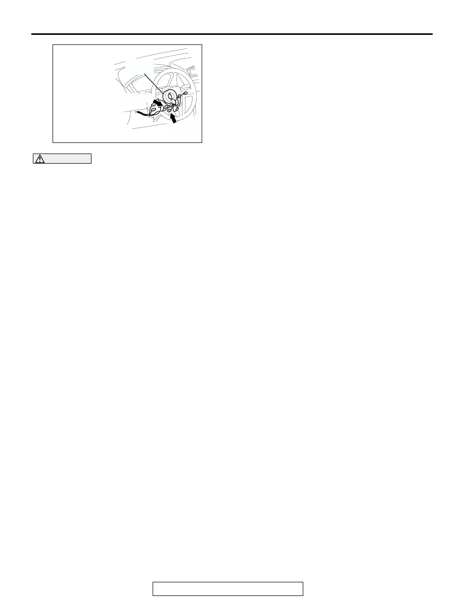
AC305235AP

C-307 (Y)

CONNECTORS: C-305, C-307

CLOCK
SPRING

C-305 (Y)

SRS AIR BAG DIAGNOSIS

TSB Revision

SUPPLEMENTAL RESTRAINT SYSTEM (SRS)

52B-50

STEP 1. Using scan tool MB991958, diagnose the CAN bus 
line.

CAUTION

To prevent damage to scan tool MB991958, always turn the 
ignition switch to the "LOCK" (OFF) position before con-
necting or disconnecting scan tool MB991958.
(1) Connect scan tool MB991958. Refer to "How to connect the 

scan tool 

P.52B-30

."

(2) Turn the ignition switch to the "ON" position.
(3) Diagnose the CAN bus line.
(4) Turn the ignition switch to the "LOCK" (OFF) position.
Q: Is the CAN bus line found to be normal?

YES : Go to Step 2.
NO :  Repair the CAN bus line (Refer to GROUP 54C, 

Diagnosis 

P.54C-14

).

STEP 2. Recheck for diagnostic trouble code.

Check again if the DTC is set.
(1) Erase the DTC.
(2) Turn the ignition switch to the "ON" position.

(3) Check if the DTC is set.
(4) Turn the ignition switch to the "LOCK" (OFF) position.
Q: Is the DTC set?

YES : Go to Step 3.
NO :  There is an intermittent malfunction such as poor 

engaged connector(s) or open circuit (Refer to 
GROUP 00, How to Cope with Intermittent 
Malfunction 

P.00-6

).

AC305412

AB

MB991910

DATA LINK

CONNECTOR

MB991824

MB991827

AC305412

AB

MB991910

DATA LINK

CONNECTOR

MB991824

MB991827

SRS AIR BAG DIAGNOSIS

TSB Revision

SUPPLEMENTAL RESTRAINT SYSTEM (SRS)

52B-51

STEP 3. Check the driver's air bag module. (Using scan 
tool MB991958, read the diagnostic trouble code.)

(1) Disconnect the negative battery terminal.
(2) Slide the outer housing of the driver’ s air bag module 

connector C-305 in the arrow direction shown, and 
disconnect the connector.

(3) Connect special tool MB991865 to special tool MB991866.

CAUTION

Do not insert a test probe into the terminal from its front 
side directly, as the connector contact pressure may be 
weakened.
(4) Insert special tool MB991866 into clock spring side of 

driver’s air bag module connector C-305 (terminal No.1 and 
2 <1st squib> or terminal No.3 and 4 <2nd squib>) by 
backprobing.

(5) Connect the negative battery terminal.
(6) Erase the diagnostic trouble code memory, and check the 

diagnostic trouble code.

Q: Is DTC B1401 <1st squib> or B1481 <2nd squib> set?

YES : Go to Step 4.
NO :  Replace the driver's air bag module. (Refer to 

P.52B-368

). Then go to Step 6.

AC306561AC

OUTER HOUSING OF THE DRIVER'S 
AIR BAG MODULE CONNECTOR C-305

AC306758 AB

C-305 AIR BAG
MODULE
CONNECTOR

MB991865
(DUMMY RESISTOR : 3

Ω)

MB991866 (RESISTOR 
HARNESS)

(REAR VIEW

)

SRS AIR BAG DIAGNOSIS

TSB Revision

SUPPLEMENTAL RESTRAINT SYSTEM (SRS)

52B-52

STEP 4. Check the clock spring. (Using scan tool 
MB991958, read the diagnostic trouble code.)

(1) Disconnect the negative battery terminal.
(2) Disconnect the clock spring connector C-307.

(3) Connect special tool MB991865 to special tool MB991866.

CAUTION

Do not insert a test probe into the terminal from its front 
side directly, as the connector contact pressure may be 
weakened.
(4) Insert special tool MB991866 into harness side of clock 

spring connector C-307 (terminal No.14 and 13 <1st squib> 
or terminal No.11 and 12 <2nd squib>) by backprobing.

(5) Connect the negative battery terminal.
(6) Erase the diagnostic trouble code memory, and check the 

diagnostic trouble code.

Q: Is DTC B1401 <1st squib> or B1481 <2nd squib> set?

YES : Go to Step 5.
NO :  Replace the clock spring. (Refer to 

P.52B-368

). Then 

go to Step 6.

AC305235AK

C-307 (Y)

CONNECTOR: C-307

C-307 HARNESS
SIDE CONNECTOR

CLOCK
SPRING

11

12

13

14

AC306767

C-307 CLOCK SPRING
CONNECTOR

AB

MB991865
(DUMMY RESISTOR : 3

Ω)

MB991866 (RESISTOR 
HARNESS)

1112

14

13

(REAR VIEW)


Content   ..  1537  1538  1539  1540   ..