Mitsubishi Galant (2004+). Manual - part 1417


  Index      Mitsubishi     Mitsubishi Galant - service repair manual 2004 year


Search            


Content   ..  1415  1416  1417  1418   ..


Mitsubishi Galant (2004+). Manual - part 1417


FRONT SEAT ASSEMBLY

TSB Revision

INTERIOR

52A-23

INSPECTION

M1522005500113

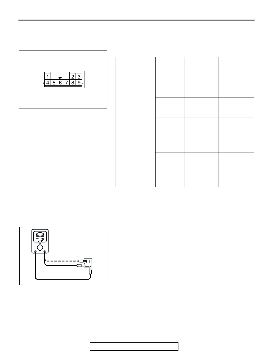
HEATED SEAT SWITCH CHECK

.

CONTINUITY TEST OF HEATED SEAT SWITCH
1. Check for continuity between terminals.

2. Check that the indicator is lighted at HI or LO when battery 

voltage is supplied to terminal 5 and terminal 8 is grounded.

3. Check that indicator is lighted when battery voltage is 

supplied to terminals 2 and terminal 6.

.

SEAT CUSHION HEATER CHECK 
Measure the resistance between terminals. 

Standard value: At room temperature 20 

°C (68 °F) 

Between terminals 2 and terminal 3: Approximately 4.0 
ohms 

± 9%

Between terminals 1 and terminal 3: 4.1 ohms 

± 9%

.

ITEM

SWITCH 
POSITION

TESTER 
CONNECTIO
N

SPECIFIED 
CONDITION

Driver's seat side HI

1 - 3, 1 - 5, 1 - 
8, 3 - 5, 3 - 8, 
5 - 8

Less than 2 
ohms

OFF

1 - 3, 1 - 5, 1 - 
8, 3 - 5, 3 - 8, 
5 - 8

Open circuit

LO

− 5, 3 − 8, 5 

− 8

Less than 2 
ohms

Front 
passenger's seat 
side

HI

4 - 5, 4 - 8, 4 - 
9, 5 - 8, 5 - 9, 
8 - 9

Less than 2 
ohms

OFF

4 - 5, 4 - 8, 4 - 
9, 5 - 8, 5 - 9, 
8 - 9

Open circuit

LO

− 8, 5 − 9, 8 

− 9

Less than 2 
ohms

AC306939 AB

HEATED SEAT SWITCH CONNECTOR

1

2 3

AC200099

FRONT SEAT ASSEMBLY

TSB Revision

INTERIOR

52A-24

SEATBACK HEATER CHECK 
Measure the resistance between terminals. 

Standard value: At room temperature 20 

°C (68 °F) 

Approximately 3.6 ohms 

± 9%

HEATED SEAT RELAY CONTINUITY CHECK

1. Remove the instrument lower cover.
2. Remove the junction block mounting and slide the junction 

block to check the heated seat.

1
2

AC200100

BATTERY VOLTAGE

TESTER 
CONNECTION

SPECIFIED 
CONDITION

Not applied

1-4

Open circuit

• Connect terminal 2 to 

the positive battery 
terminal

• Connect terminal 3 to 

the negative battery 
terminal

1-4

Less than 2 ohms

AC307021

HEATED SEAT RELAY

JUNCTION BLOCK

AB

1

4

3

2

1

3

2

4

FRONT SEAT ASSEMBLY

TSB Revision

INTERIOR

52A-25

POWER SEAT MANUAL SWITCH CONTINUITY 
CHECK

OPERATION CHECK OF POWER SEAT MOTOR

1. Disconnect the connector of each motor.
2. Check that when the battery is directly connected to the 

motor terminal, the motor turns smoothly and each adjusting 
mechanism operates as stated below for each motor:

(1) Connect the battery power supply to the terminal 1 and 

ground the terminal 2 for the rear reclining side, front 
slide side.

(2) Connect the battery power supply to the terminal 2 and 

ground the terminal 1 for the front reclining side, rear 
slide side.

(3) Connect the battery power supply to the terminal 2 and 

ground the terminal 3 for the front height down side and 
connect the battery power supply to the terminal 3 and 
ground the terminal 2 for the front height up side.

(4) Connect the battery power supply to the terminal 3 and 

ground the terminal 4 for the rear height up side and 
connect the battery power supply to the terminal 4 and 
ground the terminal 3 for the rear height down side.

3. If abnormality was found, check the power seat adjuster 

assembly.

AC210368 AB

POWER SEAT SWITCH CONNECTOR

SWITCH POSITION

TESTER CONNECTION

SPECIFIED CONDITION

Reclining switch

FRONT

2 - 9, 1 - 12

Less than 2 ohms

REAR

1 - 9, 2 - 12

Less than 2 ohms

Slide switch

FRONT

1 - 5, 2 - 6

Less than 2 ohms

REAR

2 - 5, 1 - 6

Less than 2 ohms

Front height switch

UP

1 - 7, 2 - 8

Less than 2 ohms

DOWN

2 - 7, 1 - 8

Less than 2 ohms

Rear height switch

UP

2 - 13, 1 - 14

Less than 2 ohms

DOWN

1 - 13, 2 - 14

Less than 2 ohms

+

1

2

AC307975

RECLINING
MOTOR
CONNECTOR

SLIDE MOTOR
CONNECTOR

FRONT HEIGHT
MOTOR CONNECTOR

REAR HEIGHT
MOTOR CONNECTOR

AB

FRONT SEAT ASSEMBLY

TSB Revision

INTERIOR

52A-26

DISASSEMBLY AND ASSEMBLY

M1522001500456

<LH SIDE>

WARNING

Never attempt to disassemble or repair the seat slide sensor. If faulty, replace it.

AC307987

29

27

1

25

28

32

30

30

31

31

26

11

3

4

5

7

6

8

9

2

12

14

15

13

22

17

18

21

23

20

19

24

16

10

44 ± 10 N·m 
33 ± 7 ft-lb

44 ± 10 N·m 
33 ± 7 ft-lb

44 ± 10 N·m 
33 ± 7 ft-lb

12 ± 2 N·m 
102 ± 22 in-lb

AB


Content   ..  1415  1416  1417  1418   ..