Mitsubishi Galant. Manual - part 688
SWS DIAGNOSIS
TSB Revision
SIMPLIFIED WIRING SYSTEM (SWS)
54B-147
STEP 7. Check the harness wires between ETACS-ECU
connector C-86 and battery.
NOTE: After checking junction block connector C-78 and
intermediate connector C-66, check the wires. If junction block
connector C-78 and intermediate connector C-66 are
damaged, repair or replace them. Refer to GROUP 00E,
Harness Connector Inspection
Q: Are the harness wires between ETACS-ECU connector
C-86 and battery in good condition?
YES : There is no action to be taken.
NO : Repair them. The turn-signal lights should flash
normally.
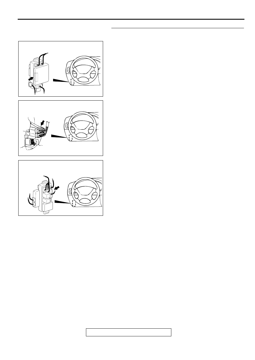
AC003080 AD
JUNCTION BLOCK
(REAR VIEW)
CONNECTOR: C-86
AC003079 AB
CONNECTOR
BLOCK (LH)
CONNECTOR: C-66
AC003082 AF
JUNCTION BLOCK
(FRONT VIEW)
CONNECTOR: C-78