Mitsubishi Galant. Manual - part 668
SWS DIAGNOSIS
TSB Revision
SIMPLIFIED WIRING SYSTEM (SWS)
54B-67
DIAGNOSIS
Required Special Tools:
•
MB991502: Scan Tool (MUT-II)
•
MB991529: Diagnostic Trouble Code Check Harness
STEP 1. Check method of the input signal
Q: Which is to be used, the scan tool or the voltmeter to
check the input signal?
Scan tool MB991502 : Go to Step 2.
Voltmeter : Go to Step 3.
STEP 2. Check the input signal (by using scan tool
MB991502).
Check the input signals from the following switches:
•
Ignition switch (IG1)
•
Driver's and front passenger's door switch
CAUTION
To prevent damage to scan tool MB991502, always turn the
ignition switch to the "LOCK" (OFF) position before
connecting or disconnecting scan tool MB991502.
(1)Connect scan tool MB991502 to the data link connector.
(2)Check that the tone alarm of scan tool MB991502 sounds
when the input signal enters.
Q: Does the tone alarm of scan tool MB991502 sound when
the input signal enters?
YES : Go to Step 4.
NO : Check the relevant input circuit. Refer to
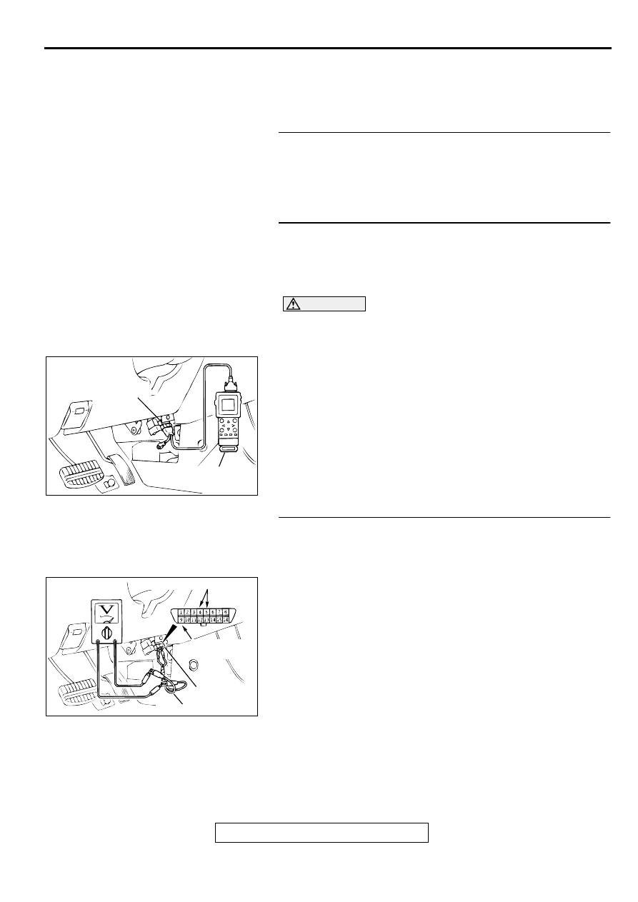
STEP 3. Check the input signal (by using a voltmeter).
Check the input signals from the following switches:
•
Ignition switch (IG1)
•
Driver's and front passenger's door switch
(1)Use special tool MB991529 to connect a voltmeter between
ground terminal 4 or 5 and ETACS-ECU terminal 9 of the
data link connector.
(2)Check that the voltmeter indicator deflects once when the
input signal enters.
Q: Does the voltmeter indicator deflect?
YES : Go to Step 4.
NO : Check the relevant input circuit. Refer to
AC003081 AB
16 PIN
MB991502
AC003083
16 PIN
AB
ETACS-ECU
TERMINAL
GROUNDED TERMINAL
MB991529