Mitsubishi Galant. Manual - part 627


  Index      Mitsubishi     Mitsubishi Galant - service repair manual 2001 year


Search            


Content   ..  625  626  627  628   ..


Mitsubishi Galant. Manual - part 627


COMBINATION METERS ASSEMBLY AND VEHICLE SPEED SENSOR

TSB Revision

CHASSIS ELECTRICAL

54A-61

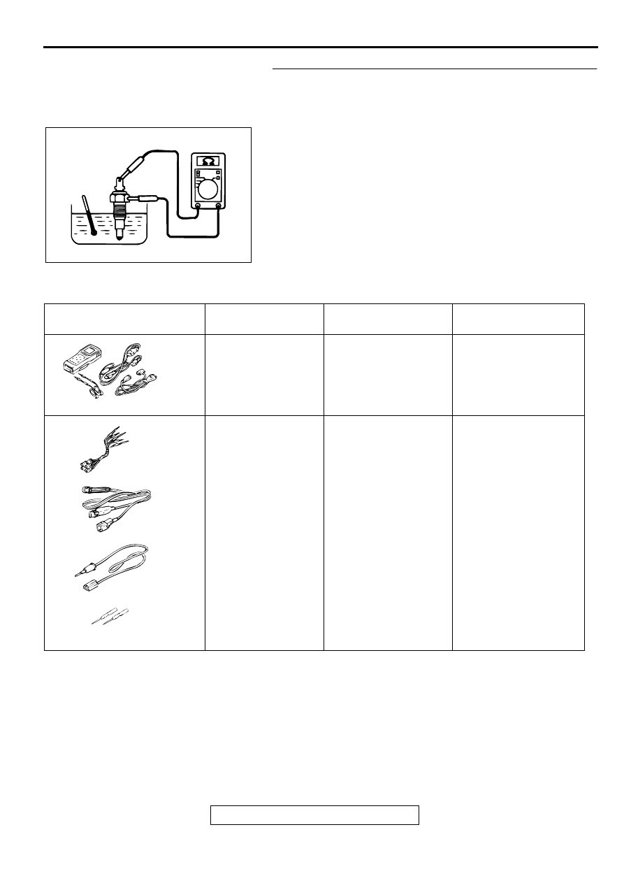
STEP 5. Check the engine coolant temperature gauge unit.
(1) Drain the engine coolant. (Refer to GROUP 00, 

Maintenance Service 

 Engine Coolant 

P.00-50

.)

(2) Remove the engine coolant temperature gauge unit.
(3) Immerse the unit in 78

°

C

 (150° 

F) water to measure the 

resistance.

Q: Is the resistance 104 

±±±±

13.5 ohms?

YES : Repair or replace the combination meter (printed-

circuit board or engine coolant temperature gauge 
assembly). The engine coolant temperature gauge 
should work normally.

NO :  Replace the engine coolant temperature gauge unit. 

The engine coolant temperature gauge should work 
normally.

SPECIAL TOOLS

M1543000600284

ACX01789 AB

TOOL

TOOL NUMBER 
AND NAME

SUPERSESSION

APPLICATION

MB991502 Scan tool 
(MUT-II)

MB991496-OD

Reading MFI system 
diagnostic trouble code

MB991223
A:MB991219
B:MB991220 
C:MB991221
D:MB991222
Harness set
A:Test harness
B:LED harness
C:LED harness 

adapter

D:Probe

MB991223

Making voltage and 
resistance 
measurements during 
troubleshooting

A:Connect pin contact 

pressure inspection

B:Power circuit 

inspection

C:Power circuit 

inspection

D:Commercial tester 

connection

B991502

MB991223

A

B

C

D

AC

TSB Revision

CHASSIS ELECTRICAL

COMBINATION METERS ASSEMBLY AND VEHICLE SPEED SENSOR

54A-62

ON-VEHICLE SERVICE

SPEEDOMETER CHECK

M1543000900100

CAUTION

Do not operate the clutch suddenly. Do not increase/
decrease speed rapidly while testing.
1. Adjust the pressure of tires to the specified level. (Refer to 

GROUP 31, On-vehicle Service 

P.13C-6

.)

2. Set the vehicle onto a speedometer tester and use wheel 

chocks to hold the rear wheels.

3. To prevent the front wheel from moving from side to side, 

attach tension bars to the tie-down hook, and secure both 
ends to anchor plates.

4. To prevent the vehicle from moving, attach a chain or wire to 

the rear retraction hook, and make sure the end of the chain 
or wire is secured.

5. Check if the speedometer indicator range is within the 

standard values.

Standard value:

6. If not to the standard value, inspect for proper tire size. If not 

correct, replace the tires with original size tires and retest. If 
correct, replace the speedometer. If still not to standard 
value, replace the vehicle speed sensor.

STANDARD INDICATION   
mph (km/h)

ALLOWANCE RANGE   mph 
(km/h)

20 (32)

19 

 22 (31 

 35)

40 (64)

38 

 44 (61 

 71)

60 (97)

57 

 66 (92 

 106)

80 (129)

76 

 88 (122 

 142)

100 (161)

94 

 110 (151 

 177)

AC001287AB

WHEEL CHOCKS

AC001288

TENSION BAR

FRONT

ANCHOR PLATE

AB

COMBINATION METERS ASSEMBLY AND VEHICLE SPEED SENSOR

TSB Revision

CHASSIS ELECTRICAL

54A-63

TACHOMETER CHECK

M1543001000100

1. Attach an external high quality tachometer to the engine 

speed detection connector on the harness side (such as 
with a paper clip).

NOTE: For tachometer check, use an external high quality 
inductive tachometer.

2. Compare the readings of the vehicle tachometer and the 

external tachometer at every engine speed, and check if the 
variations are within the standard values.

Standard values:

••••

700 r/min: 

±±±±

100 r/min

••••

3,000 r/min: 

±±±±

150 r/min

••••

5,000 r/min: 

±±±±

250 r/min

••••

6,000 r/min: 

±±±±

300 r/min

FUEL GAUGE UNIT CHECK

M1543001200104

Remove the fuel pump module and the remove the fuel gauge 
unit. (Refer to GROUP 13C, Fuel Tank 

P.13C-6

.)

FUEL GAUGE UNIT RESISTANCE

1. Check that resistance value between the fuel gauge terminal 

and ground terminal is at the standard value when the fuel 
gauge unit float is between point "F" (highest) and point "E" 
(lowest). 

Standard value:

••••

Point "F": 3 

−−−−

 5 ohms

••••

Point "E": 110 

−−−−

 112 ohms

2. Check that resistance value changes smoothly when the 

float moves slowly between point "F" (highest) and point "E" 
(lowest).

3. If all checks are correct, go to fuel gauge unit float height 

check. If any check is not correct, replace the fuel gauge 
unit.

FUEL GAUGE UNIT FLOAT HEIGHT

1. Move the float and measure height A at point "F" (highest) 

and B at point "E" (lowest) with the float arm touching 
stopper. 

Standard value:

••••

A: 180.3 mm (7.10 inches)

••••

B: 18.8 mm (0.74 inches)

2. Adjust the float arm to the standard value, then go to the 

thermistor check.

AC001289AB

TACHOMETER

ENGINE SPEED
DETECTION TERMINAL

PAPER CLIP

AC001290

FUEL GAUGE

GROUND

AB

AC001291AB

A

B

POINT "F" (HIGHEST)

ARM

POINT "E" (LOWEST)

TSB Revision

CHASSIS ELECTRICAL

COMBINATION METERS ASSEMBLY AND VEHICLE SPEED SENSOR

54A-64

THERMISTOR

CAUTION

After finishing this test, wipe the unit dry and install it in 
the fuel tank.
1. Connect the fuel gauge unit (thermistor) to the battery via a 

test light (12V 

 3.4W). Immerse in water.

2. Condition is good if the light goes off when the thermistor is 

immersed in water and comes on when it is taken out of 
water.

3. If all check result is not correct, the fuel gauge unit is OK. If 

either check result is not correct, replace the fuel gauge unit.

ENGINE COOLANT TEMPERATURE GAUGE UNIT 
CHECK

M1543001500105

1. Drain the engine coolant. (Refer to GROUP 00, 

Maintenance Service 

 Engine Coolant 

P.00-50

.)

2. Remove the engine coolant temperature gauge unit.
3. Immerse the unit in 70

°

C (150

°

F) water to measure the 

resistance.

Standard value: 104 

±±±±

 13.5 ohms

4. If within the standard value, the sensor unit is OK. Reinstall 

it, then check the engine coolant temperature gauge (Refer 
to 

P.54A-66

.) If not within the standard value, replace it.

5. After checking, apply the 3M

AAD part number 8731 

Medium strength Blue or equivalent around the threads of 
the engine coolant temperature gauge unit.

6. Add engine coolant. (Refer to GROUP 00, Maintenance 

Service 

P.00E-2

.)

AC001292

GROUND

THERMISTOR

THERMISTOR

ILLUMINATED

NOT
ILLUMINATED

AB

ACX00779

ACX00780AC

11 N·m
97 in-lb


Content   ..  625  626  627  628   ..