Mitsubishi Galant. Manual - part 468


  Index      Mitsubishi     Mitsubishi Galant - service repair manual 2001 year


Search            


Content   ..  466  467  468  469   ..


Mitsubishi Galant. Manual - part 468


TRANSAXLE

TSB Revision

AUTOMATIC TRANSAXLE OVERHAUL

23B-41

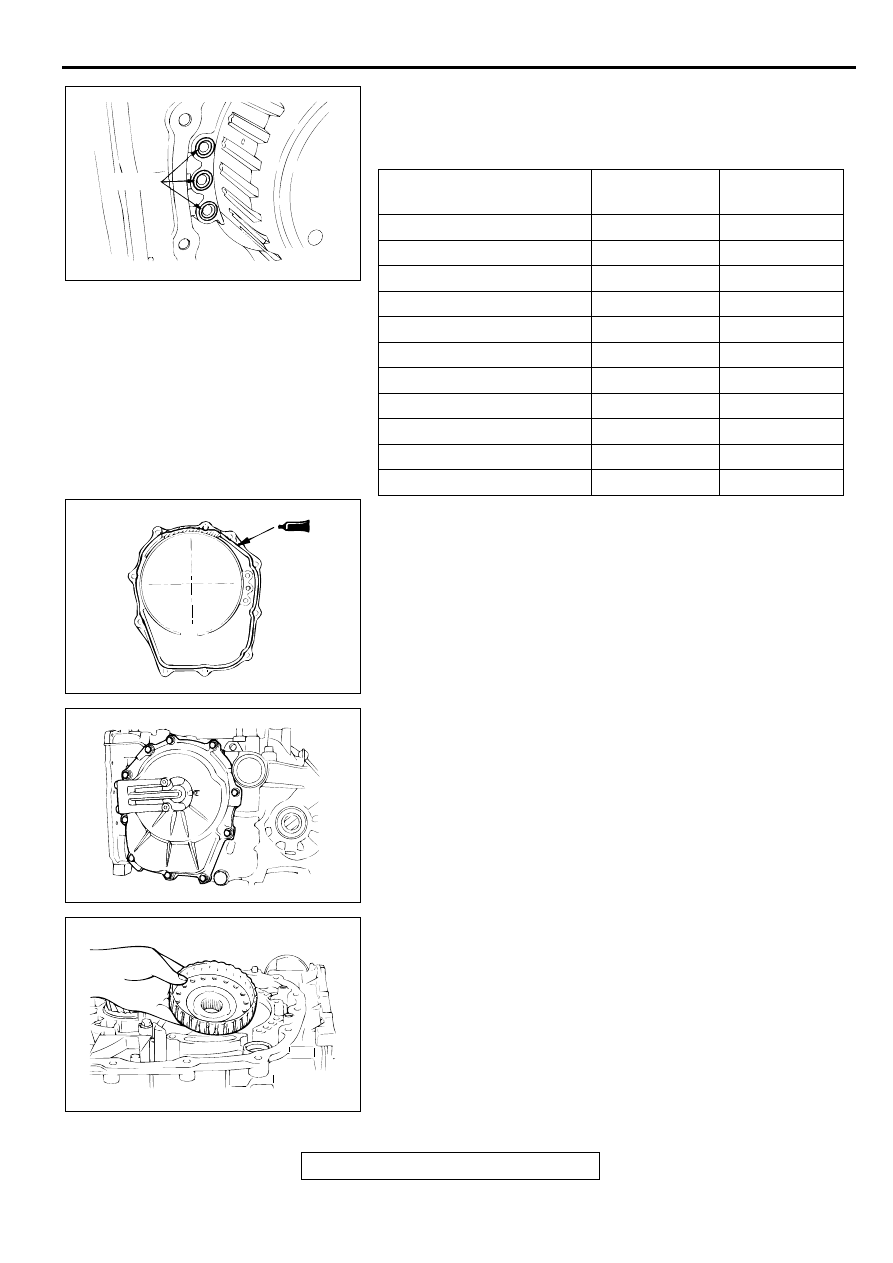
52.Install the three O-rings.

53.Select a thrust race number 8 whose thickness corresponds 

to the measured values taken in step 50 from the table 
below. Install it on thrust bearing number 7.

54.Apply a 2 mm (0.08 inch) diameter bead of sealant 

(MITSUBISHI Genuine Part number MD974421 or 
equivalent) to the illustrated position of the rear cover.

NOTE: Be sure to install the case quickly while the sealant is 
wet (within 15 minutes).

55.Install the rear cover, and tighten its mounting bolts to the 

specified torque.

Tightening torque: 23 N

⋅⋅⋅⋅

m (17  ft-lb)

NOTE: After installation, keep the sealed area away from 
the oil for approximately one hour.

56.Install the underdrive clutch hub to the underdrive sun gear.

MEASUREMENT VALUE 
mm (in)

THICKNESS 
mm (in)

PART NO.

0.3 

 0.4 (0.012 

 0.016)

1.6 (0.063)

MD707267

0.4 

 0.5 (0.016 

 0.020)

1.7 (0.067)

MD759681

0.5 

 0.6 (0.020 

 0.024)

1.8 (0.071)

MD723064

0.6 

 0.7 (0.024 

 0.028)

1.9 (0.075)

MD754794

0.7 

 0.8 (0.028 

 0.031)

2.0 (0.079)

MD707268

0.8 

 0.9 (0.031 

 0.035)

2.1 (0.083)

MD754795

0.9 

 1.0 (0.035 

 0.039)

2.2 (0.087)

MD723065

1.0 

 1.1 (0.039 

 0.043)

2.3 (0.091)

MD754796

1.1 

 1.2 (0.043 

 0.047)

2.4 (0.094)

MD724358

1.2 

 1.3 (0.047 

 0.051)

2.5 (0.098)

MD754797

1.3 

 1.4 (0.051 

 0.055)

2.6 (0.102)

MD754798

AKX01010AB

O-RINGS

AKX01073

AKX01009

AKX01032

TRANSAXLE

TSB Revision

AUTOMATIC TRANSAXLE OVERHAUL

23B-42

CAUTION

Be sure to install the thrust bearing in the correct direction 
as shown.
57.Check the installation direction of thrust bearing number 2, 

and install it on the underdrive clutch hub.

58.Hold the input shaft, and install the underdrive clutch.

59.Place two beads of solder [each 10 mm (0.39 inch) in 

length, 3.5 mm (0.14 inch) in diameter] on the underdrive 
clutch retainer as shown in the illustration.

60.Install special tool MD998412 in the illustrated place.

61.Install the oil pump to the transaxle case.

NOTE: Do not install the oil pump gasket at this time.

62.Tighten the oil pump mounting bolts (six pieces) to the 

specified torque.

Tightening torque: 23 N

⋅⋅⋅⋅

m (17  ft-lb)

AKX01089

INSTALLATION 
DIRECTION

AB

THRUST 
BEARING NO.2

AKX01030

AKX01136AB

INPUT SHAFT

TWO BEADS
OF SOLDER

UNDERDRIVE
CLUTCH RETAINER

AKX01093

MD998412

AB

TRANSAXLE

TSB Revision

AUTOMATIC TRANSAXLE OVERHAUL

23B-43

63.Remove the oil pump mounting bolts.

64.Using special tools MD998333, remove the oil pump and 

the crushed solders.

65.Use a micrometer to measure the thickness of the crushed 

solder beads and record the measured value.

66.Select a thrust washer number 1 whose thickness 

corresponds to the measured value from table below.

67.Install thrust washer number 1 that was selected in step 65 

on the underdrive clutch retainer.

68.Install special tool MD998412 in the illustrated place.

69.Install the new oil pump gasket on the transaxle case.

70.Install the oil pump and tighten the mounting bolts (six 

pieces) to the specified torque.

Tightening torque: 23 N

⋅⋅⋅⋅

m (17 ft-lb)

MEASUREMENT 
VALUE mm (in)

THICKNESS 
mm (in)

ID 
SYMBOL

PART NO.

2.25 

 2.45 (0.089 


0.096)

1.8 (0.071)

18

MD754509

2.45 

 2.65 (0.096 


0.104)

2.0 (0.079)

20

MD754508

2.65 

 2.85 (0.104 


0.112)

2.2 (0.087)

22

MD754507

2.85 

 3.05 (0.112 


0.120)

2.4 (0.094)

24

MD753793

3.05 

 3.25 (0.120 


0.128)

2.6 (0.102)

26

MD753794

3.25 

 3.45 (0.128 


0.136)

2.8 (0.110)

28

MD753795

AKX01028

MD998333

AB

AKX00958

AKX01029

THRUST WASHER 
NUMBER 1

AB

AKX01093

MD998412

AB

TRANSAXLE

TSB Revision

AUTOMATIC TRANSAXLE OVERHAUL

23B-44

71.Make sure that the input shaft end play meets the standard 

value.

Standard value: 0.70 

−−−−

 1.45 mm (0.028 

−−−−

 0.057 inch)

72.Install the oil filter.

73.Use special tools MB990935 <F4A42> or MB990936 

<F4A51> and MB990938 to tap the differential bearing outer 
race in the transaxle case.

74.Install the differential.

75.Place two beads of solder [each 10 mm (0.39 inch) in 

length, 3 mm (0.12 inch) in diameter] on the torque 
converter housing as shown in the illustration.

AKX01074

AKX01026

AKX01059

MB990938

MB990935 
<F4A42>  OR
MB990936
<F4A51>

AB

AKX01025

AKX01075

TWO BEADS 
OF SOLDER

AB


Content   ..  466  467  468  469   ..