Mitsubishi Galant. Manual - part 407


  Index      Mitsubishi     Mitsubishi Galant - service repair manual 2001 year


Search            


Content   ..  405  406  407  408   ..


Mitsubishi Galant. Manual - part 407


AUTOMATIC TRANSAXLE DIAGNOSIS

TSB Revision

AUTOMATIC TRANSAXLE

23A-95

CIRCUIT OPERATION

A coil built into the input shaft speed sensor 
generates 0 

 5 volts pulse signal at both ends 

of this coil when the input shaft rotates. The pulse 
signal frequency increases with a rise in input 
shaft speed.

Both ends of the coil are connected to the PCM 
(terminals 57 and 103) via the input shaft speed 
sensor connector (terminals 1 and 2).

The PCM detects the input shaft speed by the 
signal input to terminal 103.

The input shaft speed sensor generates the pulse 
signal as the teeth of the underdrive clutch 
retainer pass the magnetic tip of the sensor.

DTC SET CONDITIONS
If no output pulse is detected from the input shaft 
speed sensor for one second or more while driving in 
3rd or 4th gear at a speed of 30 km/h (19 mph) or 
more, it is judged to be an open circuit or short circuit 
in the input shaft speed sensor and diagnostic 
trouble code number "22" is output four times, the 
transmission is locked into 3rd gear or 2nd gear as a 
fail-safe measure.

TROUBLESHOOTING HINTS (The most likely 

causes for this code to be set:)

Malfunction of the input shaft speed sensor

Malfunction of the underdrive clutch retainer

Damaged harness, connector

Malfunction of the PCM

DIAGNOSIS

Required Special Tool:
MB991502: Scan Tool (MUT-II)

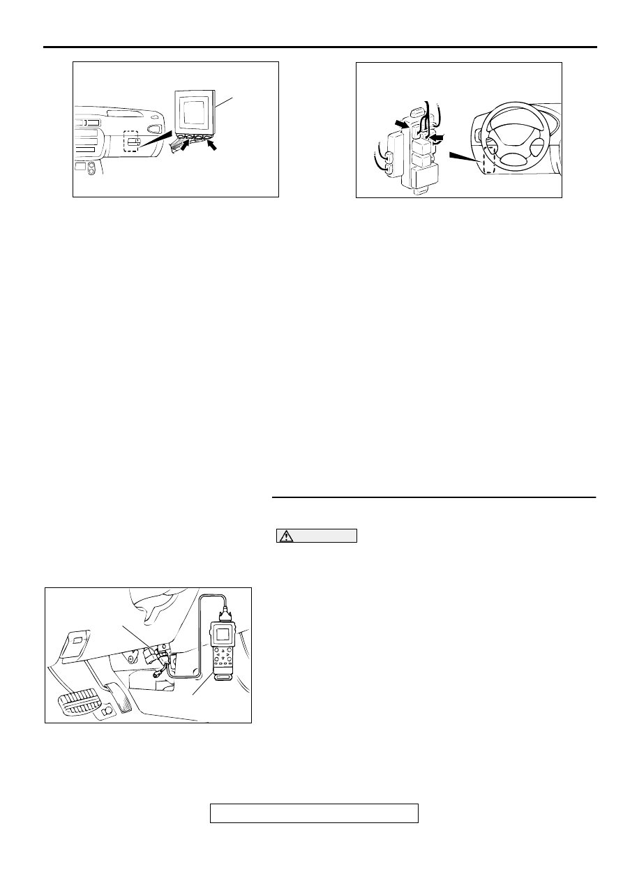
STEP 1. Using scan tool MB991502, check data list item 22: 
Input Shaft Speed Sensor.

CAUTION

To prevent damage to scan tool MB991502, always turn the 
ignition switch to "LOCK" (OFF) position before 
connecting or disconnecting scan tool MB991502.
(1) Connect scan tool MB991502 to the data link connector.
(2) Start the engine.
(3) Set scan tool MB991502 to data reading mode for item 22: 

Input Shaft Speed Sensor.

When driving at constant speed of 50km/h (31mph), the 
display should be "1,600 

 1,900 r/min." <2.4L Engine>, 

"1,300 

 1,600 r/min." <3.0L Engine> (Gear range: 3rd 

gear)

(4) Turn the ignition switch to "LOCK" (OFF) position.

Q: Is the sensor operating properly?

YES : This malfunction is intermittent. Refer to GROUP 00, 

How to Use Troubleshooting/Inspection Service 
Points 

 How to Cope with Intermittent Malfunction 

P.00-8

.

NO :  Go to Step 2.

AC004197

PCM

C-40

C-42

CONNECTORS: C-40, C-42

AE

AC004307

CONNECTORS: C-73, C-77

C-73

JUNCTION BLOCK
(FRONT VIEW)

C-77

AB

AC003081AC

MB991502

DATA LINK
CONNECTOR

AUTOMATIC TRANSAXLE DIAGNOSIS

TSB Revision

AUTOMATIC TRANSAXLE

23A-96

STEP 2. Check the ground voltage at PCM connector C-40 
by backprobing.
(1) Do not disconnect connector C-40.
(2) Turn the ignition switch to "ON" position.

(3) Measure the voltage between terminal 57 and ground by 

backprobing.

Voltage should be 0.5 volt or less.

(4) Turn the ignition switch to "LOCK" (OFF) position.

Q: Is the voltage normal?

YES : Go to Step 5.
NO :  Go to Step 3.

STEP 3. Check connector C-40 at PCM for damage.
Q: Is the connector in good condition?

YES : Go to Step 4.
NO :  Repair or replace it. Refer to GROUP 00E, Harness 

Connector Inspection 

P.00E-2

.

AC004197

PCM

AD

CONNECTOR: C-40

AC001791

C-40 CONNECTOR
HARNESS SIDE VIEW

AE

AC004197

PCM

AD

CONNECTOR: C-40

AUTOMATIC TRANSAXLE DIAGNOSIS

TSB Revision

AUTOMATIC TRANSAXLE

23A-97

STEP 4. Using scan tool MB991502, check data list item 22: 
Input Shaft Speed Sensor.

CAUTION

To prevent damage to scan tool MB991502, always turn the 
ignition switch to "LOCK" (OFF) position before 
connecting or disconnecting scan tool MB991502.
(1) Connect scan tool MB991502 to the data link connector.
(2) Start the engine.
(3) Set scan tool MB991502 to data reading mode for item 22: 

Input Shaft Speed Sensor.

When driving at constant speed of 50km/h (31mph), the 
display should be "1,600 

 1,900 r/min." <2.4L Engine>, 

"1,300 

 1,600 r/min." <3.0L Engine> (Gear range: 3rd 

gear)

(4) Turn the ignition switch to "LOCK" (OFF) position.

Q: Is the sensor operating properly?

YES : This malfunction is intermittent. Refer to GROUP 00, 

How to Use Troubleshooting/Inspection Service 
Points 

 How to Cope with Intermittent Malfunction 

P.00-8

.

NO :  Replace the PCM.

STEP 5. Check the sensor output voltage at PCM 
connector C-42 by backprobing.
(1) Do not disconnect connector C-42.
(2) Disconnect connector C-16 at the input shaft speed sensor.
(3) Turn the ignition switch to "ON" position.

(4) Measure the voltage between terminal 103 and ground by 

backprobing.

Voltage should be between 4.8 and 5.2 volts.

(5) Turn the ignition switch to "LOCK" (OFF) position.

Q: Is the voltage normal?

YES : Go to Step 8.
NO :  Go to Step 6.

AC003081AC

MB991502

DATA LINK
CONNECTOR

AC004197

PCM

AF

CONNECTOR: C-42

AC001810

C-42 CONNECTOR
HARNESS SIDE VIEW

AE

AUTOMATIC TRANSAXLE DIAGNOSIS

TSB Revision

AUTOMATIC TRANSAXLE

23A-98

STEP 6. Check connectors C-42 at PCM and B-40 at input 
shaft speed sensor for damage.
Q: Are the connectors in good condition?

YES : Go to Step 7.
NO :  Repair or replace it. Refer to GROUP 00E, Harness 

Connector Inspection 

P.00E-2

.

STEP 7. Check harness for short circuit to ground between 
PCM connector C-42 terminal 103 and input shaft speed 
sensor connector B-40 terminal 2.
Q: Is the harness wire in good condition?

YES : Go to Step 4.
NO :  Repair it.

AC004197

PCM

AF

CONNECTOR: C-42

AC001835

CONNECTOR: B-40

AF

AC004197

PCM

AF

CONNECTOR: C-42

AC001835

CONNECTOR: B-40

AF


Content   ..  405  406  407  408   ..