Mitsubishi Galant. Manual - part 387


  Index      Mitsubishi     Mitsubishi Galant - service repair manual 2001 year


Search            


Content   ..  385  386  387  388   ..


Mitsubishi Galant. Manual - part 387


AUTOMATIC TRANSAXLE DIAGNOSIS

TSB Revision

AUTOMATIC TRANSAXLE

23A-15

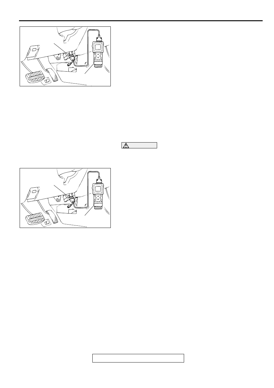
1. Connect the scan tool MB991502 to the data link connector.

2. Turn the ignition switch to "ON" position.

3. Record the diagnostic trouble codes for A/T.

4. Refer to the Diagnostic Trouble Code Chart.

5. Turn the ignition switch to "LOCK" (OFF) and then back to 

"ON" again.

6. Erase the diagnostic trouble code by selecting DTC erase 

from SPECIAL MENU screen, using scan tool.

7. Check for diagnostic trouble codes. Confirm the scan tool 

displays "normal."

8. Turn the ignition switch to "LOCK" (OFF) position.

9. Disconnect the scan tool.

INSPECTION USING SCAN TOOL, ROAD TEST 
AND DATA LIST

Required Special Tool:
MB991502: Scan Tool (MUT-II)

CAUTION

To prevent damage to scan tool MB991502, always turn the 
ignition switch to "LOCK" (OFF) position before 
connecting or disconnecting scan tool MB991502.
1. Connect the scan tool MB991502 to data link connector.

2. Turn the ignition switch to "ON" position.

3. Carry out inspection by means of the Road Test or Data List 

function. If there is an abnormality, check and repair the 
chassis harnesses and components. Refer to 

P.23A-17

Road Test. Refer to 

P.23A-259

, Data List Reference Table.

4. Re-check using scan tool and check that the abnormal input 

and output have returned to normal because of the repairs.

5. Erase the diagnostic trouble code(s).

6. Turn the ignition switch to "LOCK" (OFF) position.

7. Disconnect the scan tool from the data link connector.

8. Start the engine again and do a test drive to confirm that the 

problem is eliminated.

FAIL-SAFE/BACKUP FUNCTION

M1231008300052

When malfunctions of the main sensors or actuators 
are detected by the PCM, the transaxle is controlled 
by pre-set control logic to maintain safe conditions 
for driving.

AC003081AC

MB991502

DATA LINK
CONNECTOR

AC003081AC

MB991502

DATA LINK
CONNECTOR

AUTOMATIC TRANSAXLE DIAGNOSIS

TSB Revision

AUTOMATIC TRANSAXLE

23A-16

MALFUNCTIONING 
ITEM

JUDGEMENT 
CONDITION

CONTROL CONTENTS DURING MALFUNCTION

Input shaft speed sensor No output pulse from the 

input shaft speed sensor is 
detected for one second or 
more when the vehicle 
speed is 30 km/h (19 mph) 
or more.

The diagnostic trouble code is displayed when the 
judgement condition occurs once. When the judge-
ment condition is met four times, the transaxle holds 
3rd gear or 2nd gear depending on speed as a fail-
safe.

Output shaft speed sen-
sor

Output from the output 
shaft speed sensor is con-
tinuously 50 % or less of 
the output from the vehicle 
speed sensor one second 
or more when the vehicle 
speed is 30 km/h (19 mph) 
or more.

The diagnostic trouble code is displayed when the 
judgement condition occurs once. When the judge-
ment condition is met four times, the transaxle holds 
3rd gear or 2nd gear depending on speed as a fail-
safe.

Low-reverse solenoid 
valve

Solenoid valve resistance 
is below 2.7 W for 0.32 
seconds.

When the judgement condition is met four times, the 
A/T control relay is turned off.

Underdrive solenoid 
valve

Second solenoid valve

Overdrive solenoid valve

Torque converter clutch 
solenoid valve

Incomplete 
shifting

1st

Gear ratio value which is 
sent from the output shaft 
speed sensor is not identi-
cal to the output from the 
input shaft speed sensor 
for one second after shift-
ing finished.

The diagnostic trouble code is displayed and the 
judgement condition occurs once. When the judge-
ment condition is met four times, the A/T control re-
lay is turned off.

2nd

3rd

4th

Reverse

A/T control relay

A/T control relay voltage is 
less than seven volts for 
0.1 second after the igni-
tion switch is turned "ON."

Switch the A/T control relay off.

Abnormality in the PCM

Abnormality has occurred 
in the PCM.

Switch the A/T control relay off.

AUTOMATIC TRANSAXLE DIAGNOSIS

TSB Revision

AUTOMATIC TRANSAXLE

23A-17

ROAD TEST

M1231007800054

Check by the following procedures

STEP CONDITION 

BEFORE TEST/
OPERATION

TEST/OPERATION

STANDARD

INSPECTI
ON ITEM

DTC

INSPECTION 
PROCEDURE 
PAGE

1

Ignition switch: 
(LOCK) OFF

Ignition switch
(1) ON

Data list No. 54

(1) Control 

Relay Voltage 
[V]

A/T Control 
relay 
output 
voltage

54

A/T Control 
relay system 
(

P.23A-208

.)

2

Ignition switch: 
ON
Engine: Stopped
Selector lever 
position: P

Selector lever position
(1) P, (2) R, (3) N, (4) D, 
(5) 3, (6) 2, (7) L

Data list No. 61
(1) P, (2) R, (3) 
N, (4) D, (5) 3, 
(6) 2, (7) L

Park/
Neutral 
position 
switch

27, 
28

Park/Neutral 
position switch 
system (

P.23A-

124

P.23A-

143

.)

Accelerator pedal
(1)Fully closed
(2)Depressed
(3)Fully open

Data list No. 11
(1)535 

 735 mV

(2)Gradually 
rises from (1)
(3)4,500 

 5,500 

mV

TPS

11, 
12, 
14

TPS system 
(

P.23A-39

P.23A-48

P.23A-56

.)

Brake pedal
(1)Depressed
(2)Released

Data list No. 26
(1)ON
(2)OFF

Stoplight 
switch

26

Stoplight 
switch system 
(

P.23A-117

.)

3

Ignition switch: 
ST
Engine: Stopped

Starting test with 
lever in P or N range

Starting should 
be possible

Starting

-

Vehicles does 
not move 
(

P.23A-216

.)

4

Warming up

Drive for 15 minutes or 
more so that the A/T fluid 
temperature becomes 70 

 80

°

C. (158 

 176

°

F)

Data list No. 15
Gradually rises 
to 70 

 80

°

(158 

 176

°

F)

A/T fluid 
temperatur
e sensor

15, 
16

A/T fluid 
temperature 
sensor system 
(

P.23A-66

P.23A-73

.)

5

Engine: Idling
Selector lever 
position: N

Brake pedal (Retest)
(1)Depressed
(2)Released

Data list No. 26
(1)ON
(2)OFF

Stoplight 
switch

26

Stoplight 
switch system 
(

P.23A-117

.)

A/C switch
(1)ON
(2)OFF

Data list No. 65
(1)ON
(2)OFF

Dual 
pressure 
switch

-

Vehicle shifts 
differently with 
A/C engaged 
(

P.23A-247

.)

Accelerator pedal
(1)Fully closed
(2)Depressed

Data list No. 21
(1)Engine 
tachometer and 
the MUT-II 
shows the same 
engine speed
(2)Gradually 
rises from (1)

Crankshaft 
position 
sensor

21

Crankshaft 
position sensor 
system (

P.23A-

78

.)

AUTOMATIC TRANSAXLE DIAGNOSIS

TSB Revision

AUTOMATIC TRANSAXLE

23A-18

5

Engine: Idling
Selector lever 
position: N

Selector lever position
(1)N 

 D

(2)N 

 R

Should be no 
abnormal shift 
shocks
Time delay when 
engaging should 
be within 2 
seconds

Malfunction 
when 
starting

-

Engine stalls 
when moving 
selector lever 
from N to D or 
N to R (

P.23A-

224

.)

-

Shift shocks 
when shifting 
from N to D 
and long delay 
(

P.23A-225

.)

-

Shift shocks 
when shifting 
from N to R 
and long delay 
(

P.23A-228

.)

-

Shift shocks 
when shifting 
from N to D, N 
to R and long 
delay (

P.23A-

231

.)

Does not 
move

-

Does not move 
forward 
(

P.23A-218

.)

-

Does not move 
backward 
(

P.23A-220

.)

-

Does not move 
(forward or 
backward) 
(

P.23A-223

.)

STEP CONDITION 

BEFORE TEST/
OPERATION

TEST/OPERATION

STANDARD

INSPECTI
ON ITEM

DTC

INSPECTION 
PROCEDURE 
PAGE


Content   ..  385  386  387  388   ..