Mitsubishi Galant. Manual - part 218


  Index      Mitsubishi     Mitsubishi Galant - service repair manual 2001 year


Search            


Content   ..  216  217  218  219   ..


Mitsubishi Galant. Manual - part 218


MULTIPORT FUEL INJECTION(MFI) DIAGNOSIS

TSB Revision

MULTIPORT FUEL INJECTION (MFI) <3.0L>

13B-97

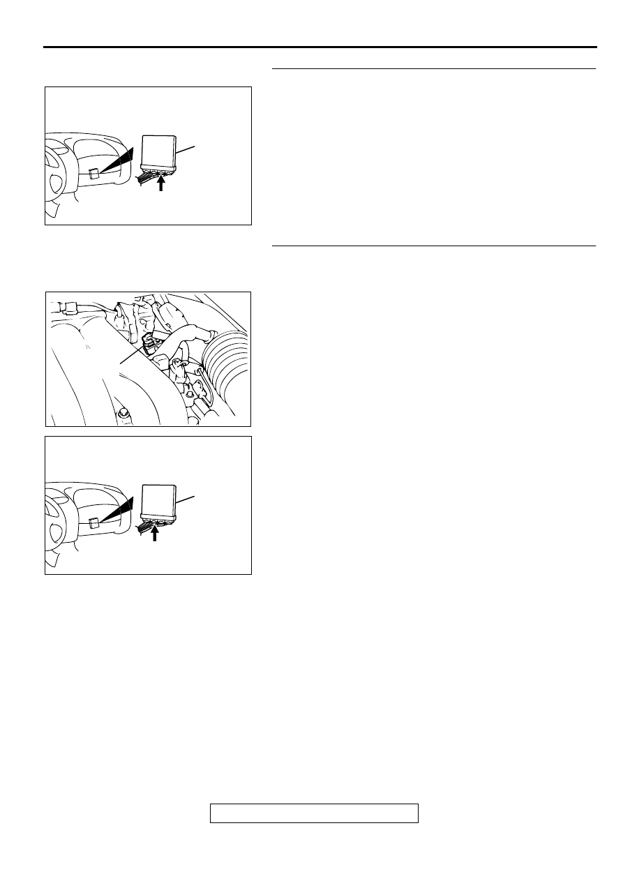
STEP 5. Check connector C-41 at PCM for damage.
Q: Is the connector in good condition?

YES : Go to Step 6.
NO :  Repair or replace it. Refer to GROUP 00E, Harness 

Connector Inspection(

P.00E-2

). Then go to Step 9.

STEP 6. Check for harness damage between throttle 
position sensor connector B-05 terminal 4 and PCM 
connector C-40 terminal 46.
Q: Is the harness wire in good condition?

YES : Go to Step 7.
NO :  Repair it. Then go to Step 9.

AK000280

CONNECTOR : C-41

PCM

AY

ACX02484 AH

THROTTLE
POSITION
SENSOR

CONNECTOR:B-05

AK000280

CONNECTOR : C-40

PCM

AV

MULTIPORT FUEL INJECTION(MFI) DIAGNOSIS

TSB Revision

MULTIPORT FUEL INJECTION (MFI) <3.0L>

13B-98

STEP 7. Check for harness damage between throttle 
position sensor connector B-05 terminal 3 and PCM 
connector C-41 terminal 78.
Q: Is the harness wire in good condition?

YES : Go to Step 8.
NO :  Repair it. Then go to Step 9.

STEP 8. Using scan tool MB991502, check data list item 14: 
Throttle Position Sensor.

CAUTION

To prevent damage to scan tool MB991502, always turn the 
ignition switch to the "LOCK"(OFF) position before 
connecting or disconnecting scan tool MB991502.
(1) Connect scan tool MB991502 to the data link connector.
(2) Turn the ignition switch to the "ON" position.
(3) Set scan tool MB991502 to the data reading mode for item 

14, Throttle Position Sensor.

With the throttle valve in the idle position, voltage should 
be between 0.535 and 0.735 volts.

With the throttle valve in the full-open position, voltage 
should be between 4.5 and 5.5 volts.

(4) Turn the ignition switch to the "LOCK"(OFF) position.

Q: Is the sensor operating properly?

YES : It can be assumed that this malfunction is intermittent. 

Refer to GROUP 00, How to Use Troubleshooting/
Inspection Service Points(

P.00-8

).

NO :  Replace the PCM. Then go to Step 9.

ACX02484 AH

THROTTLE
POSITION
SENSOR

CONNECTOR:B-05

AK000280

CONNECTOR : C-41

PCM

AY

AC003081 AB

16 PIN

MB991502

MULTIPORT FUEL INJECTION(MFI) DIAGNOSIS

TSB Revision

MULTIPORT FUEL INJECTION (MFI) <3.0L>

13B-99

STEP 9. Test the OBD-II drive cycle.
(1) Carry out a test drive with the drive cycle pattern. Refer to 

P.13B-4

, Procedure 6 

 Other Monitor.

(2) Check the diagnostic trouble code (DTC).

Q: Is the DTC P0122 is output?

YES : Retry the troubleshooting.
NO :  The inspection is complete.

MULTIPORT FUEL INJECTION(MFI) DIAGNOSIS

TSB Revision

MULTIPORT FUEL INJECTION (MFI) <3.0L>

13B-100

DTC P0123: Throttle Position Circuit High Input

AK000500

2 3 4

1

GREEN-YELLO

W

BR

O

WN-

WHITE

BR

O

WN-

WHITE

BLA

CK

98

78

71

88 89

76 77

72
79
91

73
80

74

75

81
92

82 83
93

84 85

94

86 87

95 96

90

97

57

78

46

5V

AUTO-CRUISE
CONTROL SYSTEM

      B-05
(MU802724)

THROTTLE POSITION
SENSOR

4

3

1

POWERTRAIN CONTROL
MODULE(PCM)

      C-41
(MU803782)

      C-40
(MU803781)

42 43
48 49 50 51 52 53 54 55 56 57

46

45

44

58 59

60 61 62 63

64 65 66

47

41


Content   ..  216  217  218  219   ..