Mitsubishi Galant. Manual - part 106
MULTIPORT FUEL INJECTION(MFI) DIAGNOSIS
TSB Revision
MULTIPORT FUEL INJECTION (MFI) <2.4L>
13A-105
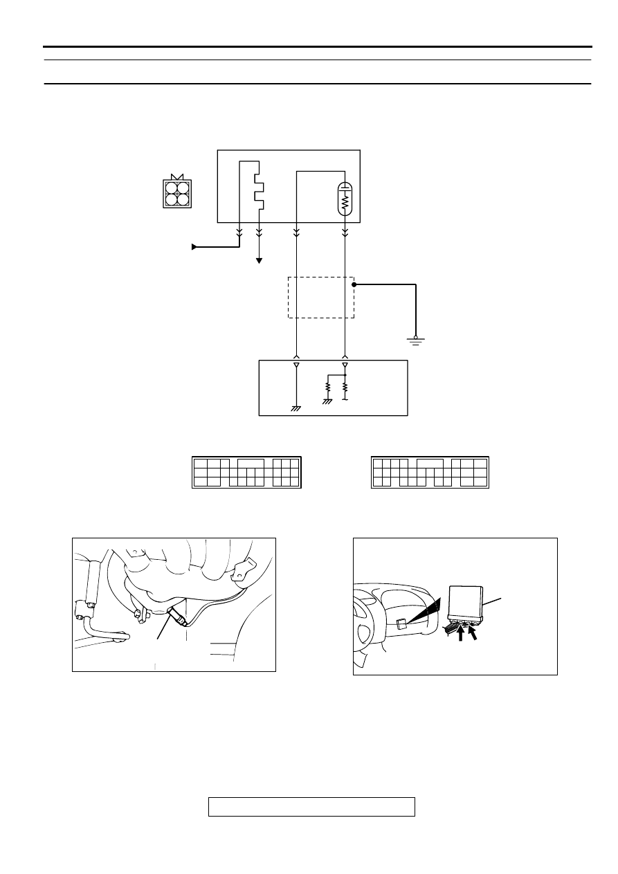
DTC P0130: O
2
Sensor Circuit Malfunction (sensor 1)
CIRCUIT OPERATION
•
A voltage corresponding to the oxygen
concentration in the exhaust gas is sent to the
PCM (terminal 71) from the output terminal
(terminal 4) of the heated oxygen sensor (front).
•
Terminal 2 of the heated oxygen sensor (front) is
grounded with PCM (terminal 57).
TECHNICAL DESCRIPTION
•
The heated oxygen sensor (front) detects the
concentration of oxygen in the exhaust gas; it
converts those data to voltage, and inputs the
resulting signals to the PCM.
AK000464
4
1 2
3
BLA
CK
BLA
CK
WHITE
B-15
MU802605
POWERTRAIN CONTROL
MODULE(PCM)
HEATED OXYGEN
SENSOR(FRONT)
FROM MFI RELAY
TO ECM
OR PCM
1
2
3
4
57
71
C-40
(MU803781)
C-41
(MU803782)
98
78
71
88 89
76 77
72
79
91
73
80
74
75
81
92
8283
93
8485
94
8687
9596
90
97
42 43
48 49 50 51 52 53 54 55 56 57
46
45
44
58 59
60 61 62 63
64 65 66
47
41
ACX02476
CONNECTOR : B-15
AF
HEATED OXYGEN
SENSOR (FRONT)
AK000280
CONNECTORS : C-40, C-41
C-41
C-40
PCM
AX