Mitsubishi Galant. Manual - part 89


  Index      Mitsubishi     Mitsubishi Galant - service repair manual 2001 year


Search            


Content   ..  87  88  89  90   ..


Mitsubishi Galant. Manual - part 89


MULTIPORT FUEL INJECTION(MFI) DIAGNOSIS

TSB Revision

MULTIPORT FUEL INJECTION (MFI) <2.4L>

13A-37

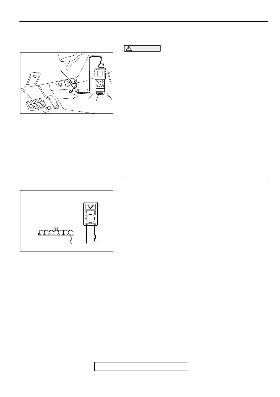
STEP 1. Using scan tool MB991502, check data list item 12: 
Volume Air Flow Sensor.

CAUTION

To prevent damage to scan tool MB991502, always turn the 
ignition switch to the "LOCK" (OFF) position before 
connecting or disconnecting scan tool MB991502.
(1) Connect scan tool MB991502 to the data link connector.
(2) Start the engine and run at idle.
(3) Set scan tool MB991502 to the data reading mode for item 

12, Volume Air Flow Sensor.

(4) Warm up the engine to normal operating temperature:80

°

 C 

to 96

°

 C(176

° 

F to 205

° 

F).

The standard value during idling should be 10Hz or 
more.

When the engine is revved, the frequency should 
increase according to the increase in engine speed.

(5) Turn the ignition switch to the "LOCK" (OFF) position.

Q: Is the sensor operating properly?

YES : It can be assumed that this malfunction is intermittent. 

Refer to GROUP 00, How to Use Troubleshooting/
Inspection Service Points(

P.00-8

).

NO :  Go to Step 2.

STEP 2. Check the reset signal voltage at volume air flow 
sensor connector B-14 by backprobing
(1) Do not disconnect the connector B-14.
(2) Turn the ignition switch to the "ON" position.
(3) Measure the voltage between terminal 7 and ground by 

backprobing.

Voltage should be between 6.0 and 9.0 volts.

(4) Turn the ignition switch to the "LOCK" (OFF) position.

Q: Is the voltage normal?

YES : Go to Step 5.
NO :  Go to Step 3.

AC003081 AB

16 PIN

MB991502

AKX01515 AC

B-14 CONNECTOR
HARNESS
SIDE VIEW

1 2 3 4 5 6 7

MULTIPORT FUEL INJECTION(MFI) DIAGNOSIS

TSB Revision

MULTIPORT FUEL INJECTION (MFI) <2.4L>

13A-38

STEP 3. Check connector B-14 at volume air flow sensor 
and connector C-39 at PCM for damage.
Q: Is the connector in good condition?

YES : Go to Step 4.
NO :  Repair or replace it. Refer to GROUP 00E, Harness 

Connector Inspection(

P.00E-2

). Then go to Step 9.

STEP 4. Check for short circuit to ground between volume 
air flow sensor connector B-14 terminal 7 and PCM 
connector C-39 terminal 19.
Q: Is the harness wire in good condition?

YES : Replace the volume air flow sensor. Then go to Step 

9. 

NO :  Repair it. Then go to Step 9.

ACX02480

CONNECTOR : B-14

AC

VOLUME AIR
FLOW SENSOR

AK000280

CONNECTOR : C-39

PCM

AW

ACX02480

CONNECTOR : B-14

AC

VOLUME AIR
FLOW SENSOR

AK000280

CONNECTOR : C-39

PCM

AW

MULTIPORT FUEL INJECTION(MFI) DIAGNOSIS

TSB Revision

MULTIPORT FUEL INJECTION (MFI) <2.4L>

13A-39

STEP 5. Check the reset signal voltage at volume air flow 
sensor connector B-14 by backprobing.
(1) Do not disconnect the connector B-14.
(2) Start the engine and run at idle.
(3) Measure the voltage between terminal 7 and ground by 

backprobing.

When the engine idling, voltage should be 1.0 volt or 
less.

When the engine speed is 3000r/min, voltage should be 
between 6.0 and 9.0 volts.

(4) Turn the ignition switch to the "LOCK" (OFF) position.

Q: Is the voltage normal?

YES : Go to Step 8.
NO :  Go to Step 6.

STEP 6. Check connector B-14 at volume air flow sensor 
and connector C-39 at PCM for damage.
Q: Is the connector in good condition?

YES : Go to Step 7.
NO :  Repair or replace it. Refer to GROUP 00E, Harness 

Connector Inspection(

P.00E-2

). Then go to Step 9.

AKX01515 AC

B-14 CONNECTOR
HARNESS
SIDE VIEW

1 2 3 4 5 6 7

ACX02480

CONNECTOR : B-14

AC

VOLUME AIR
FLOW SENSOR

AK000280

CONNECTOR : C-39

PCM

AW

MULTIPORT FUEL INJECTION(MFI) DIAGNOSIS

TSB Revision

MULTIPORT FUEL INJECTION (MFI) <2.4L>

13A-40

STEP 7. Check for open circuit and harness damage 
between volume air flow sensor connector B-14 terminal 7 
and PCM connector C-39 terminal 19.
Q: Is the harness wire in good condition?

YES : Replace the PCM. Then go to Step 9.
NO :  Repair it. Then go to Step 9.

STEP 8. Replace the volume air flow sensor.
(1) Replace the volume air flow sensor.
(2) Carry out a test drive with the drive cycle pattern. Refer to, 

Procedure 6 

 Other Monitor(

P.13A-5

).

(3) Check the diagnostic trouble code (DTC).

Q: Is the DTC P0103 is output?

YES : Replace the PCM. Then go to Step 9.
NO :  The inspection is complete.

STEP 9. Test the OBD-II drive cycle.
(1) Carry out a test drive with the drive cycle pattern. Refer to, 

Procedure 6 

 Other Monitor(

P.13A-5

).

(2) Check the diagnostic trouble code (DTC).

Q: Is the DTC P0103 is output?

YES : Retry the troubleshooting.
NO :  The inspection is complete.

ACX02480

CONNECTOR : B-14

AC

VOLUME AIR
FLOW SENSOR

AK000280

CONNECTOR : C-39

PCM

AW

ACX02480

CONNECTOR : B-14

AC

VOLUME AIR
FLOW SENSOR


Content   ..  87  88  89  90   ..