Mitsubishi Galant. Manual - part 10
MAINTENANCE SERVICE
TSB Revision
GENERAL <BODY AND CHASSIS>
00-37
Sever usage conditions:
A: Driving in dusty conditions
B: Trailer towing, or police, taxi, or commercial type operation
C: Extensive idling, driving in stop and go traffic
D: Short-trip operation at freezing temperatures (engine not thoroughly warmed up)
E: Driving in sandy areas
F: Driving in salty areas
G: More than 50% operation in heavy city traffic or at sustained high speeds during hot weather above 32
°
C
(90
°Φ)
H: Driving off-road
M A IN TEN A N C E SERVIC E
1. FUEL SYSTEM
−−−−
TANK, PIPE LINES,
CONNECTIONS AND FUEL TANK FILLER TUBE
CAP (CHECK FOR LEAKS)
M1001001600118
1. Check for damage or leakage in the fuel lines and
connections.
2. Inspect the surface of fuel hoses for heat and mechanical
damage. Hard and brittle rubber, cracking, checking, tears,
cuts, abrasions and excessive swelling indicate deterioration
of the rubber.
3. If the fabric casing of the rubber hose is exposed by cracks
and abrasions in the fuel system, the hoses should be
replaced.
2. FUEL HOSES (CHECK CONDITION)
M1001001700115
1. Inspect the surface of fuel hoses for heat and mechanical
damage.Hard and brittle rubber, cracking, checking, tears,
cuts, abrasions and excessive swelling indicate deterioration
of the rubber.
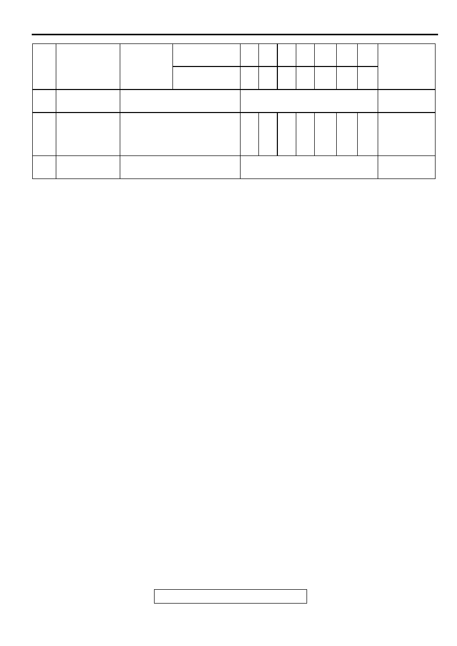
14
Disc brake
pads
Inspect for wear every 6
months or
Every 9,600 km (6,000 miles)
A and F
15
Rear drum
brake linings
and rear wheel
cylinders
Inspect for wear and leaks
every 12 months or
X
X
X
X
X
X
X
A and F
21
Tires
Rotate every 6 months or
Every 9,600 km (6,000 miles)
B,C,E,G and
H
NO.
MAINTNANCE
ITEM
SERVICE
INTERVALS
KILOMETERS
IN THOUANDS
24
48
72
96
120
144 168 SEVERE
USAGE
CONDIIONS
MILEAGE IN
THOUSANDS
15
30
45
60
75
90
105