Mitsubishi Pajero Pinin. Manual - part 351


  Index      Mitsubishi     Mitsubishi Pajero Pinin - service repair manual 2001 year


Search            


Content   ..  349  350  351  352   ..


Mitsubishi Pajero Pinin. Manual - part 351


SWS – 

Troubleshooting

54B-6

TROUBLESHOOTING

STANDARD FLOW OF DIAGNOSTIC TROUBLESHOOTING

Refer to GROUP 00 – How to Use Troubleshooting/Inspection Service Points.

DIAGNOSTIC FUNCTION

DIAGNOSIS CODES CHECK

Use the MUT-

II

 to check a diagnosis code.

(Refer to GROUP 00 – How to Use Troubleshooting/Inspection Service Points.)

NOTE
Connect the MUT-

II

 to the 16-pin diagnosis connector (black).

INPUT SIGNAL CHECK

1.

Use the MUT-

II

 to check a input signal.

(Refer to GROUP 00 – How to Use Troubleshooting/Inspection Service Points.)

2.

In this condition, the following input switches can be checked.

3.

If an abnormality is found during the input signal check, carry out troubleshooting while referring to
the Trouble Symptom Check page.

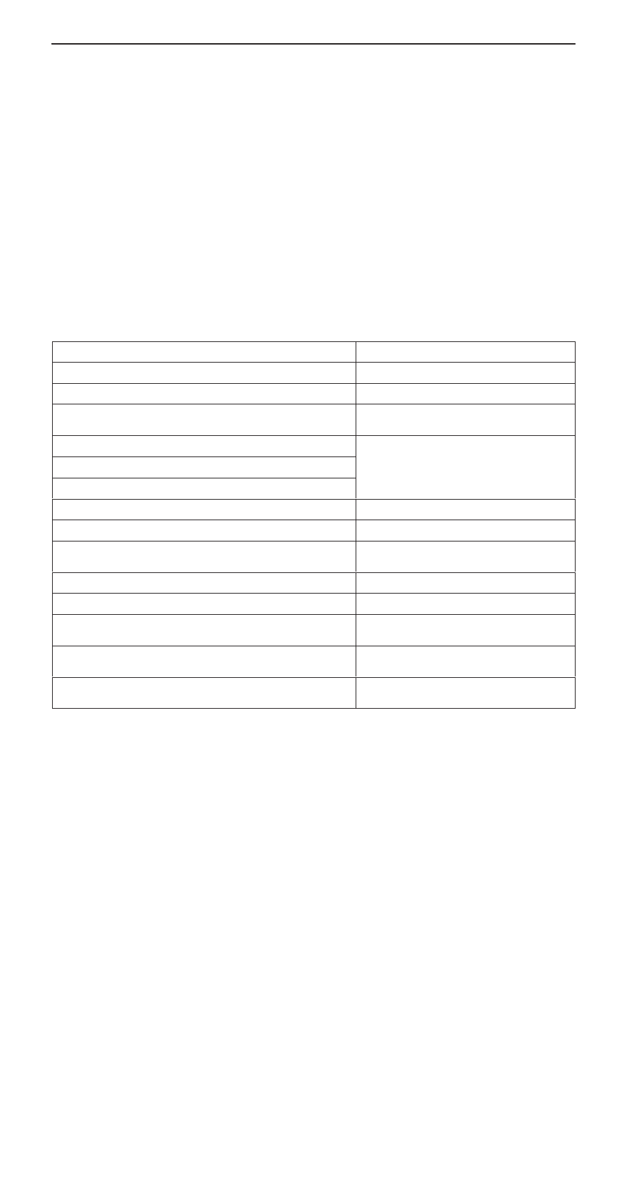
Input Signal Check Function

Input signal

Buzzer operation condition

Ignition switch (ACC)

Turned from LOCK (OFF) to ACC

Ignition switch (IG1)

Turned from ACC to ON

Key reminder switch

Ignition key removed from ignition key cylinder
(from inserted position)

Hazard warning lamp switch

Turned from OFF to ON

Front fog lamp switch <vehicles with front fog lamp>

Rear fog lamp switch

Back-up lamp switch <M/T>

Shift lever moved to R position

Inhibitor switch (reverse) <A/T>

Selector lever moved to R position

Rear wiper motor auto-stop signal

Rear wiper begins to operate (The input signal
is sent before the rear wiper begins to operate)

Driver’s door switch

Driver’s door opened from closed condition

Door switches

All doors closed to any door opened

Passenger’s door key cylinder switch <vehicles with central door
locking system>

Passenger’s door locked or unlocked using
ignition key

Back door key cylinder switch <vehicles with central door locking
system>

Back door locked or unlocked using ignition key

Driver’s door lock actuator switch <vehicles with central door locking
system>

Driver’s door lock knob moved from lock
position to unlock position or vice versa

SWS – 

Troubleshooting

54B-7

Input signal

Buzzer operation condition

Column switch

Tail lamp switch

Turned the lighting switch from OFF to tail lamp
position

Headlamp switch

Turn the lighting switch from tail lamp position to
headlamp position

Dimmer switch

Turned from OFF to ON

Passing switch

Turn-signal lamp switch

Windshield mist wiper switch

Windshield intermittent wiper switch

Windshield low-speed wiper switch

Windshield high-speed wiper switch

Windshield intermittent wiper interval adjusting
knob <vehicles with variable windshield inter-
mittent wiper>

Rotate the windshield intermittent wiper interval
adjusting knob from FAST to SLOW when the
ignition switch is at ON position (The ETACS-
ECU sends a signal around the medium knob
position)

Windshield washer switch

Turned from OFF to ON

Rear wiper switch

Rear washer switch

Headlamp washer switch <vehicles with head-
lamp washer>

Power window
main switch

Any switch <vehicles with power window>

Transmitter

Any switch <vehicles with keyless entry
system>

Multi-center dis-
play

Any switch <vehicles with multi-center display>

DIAGNOSIS CODE CHART

Code No.

Diagnosis item

Reference page

11

Failure concerning the ETACS-ECU

54B-8

12

Failure concerning the column switch or improper connecting with the ETACS-ECU

54B-8

13

Failure concerning the front-ECU

54B-9

21

Short circuit in communication line

54B-10

SWS – 

Troubleshooting

54B-8

DIAGNOSIS CODE INSPECTION PROCEDURES

Code No.11 Failure concerning the ETACS-ECU

Probable cause

The ETACS-ECU monitors its own communication data, and sends a diagnosis
code when an error takes place consecutive fifteen times in 0.6 second.
The diagnosis code will be erased when the ETACS-ECU determines that its
own communication data is sent consecutive 15 times in 0.6 second.

D

Malfunction of ETACS-ECU

Replace the ETACS-ECU.

Code No.12 Failure concerning the column switch or
improper connection with the ETACS-ECU

Probable cause

This diagnosis code is displayed when the column switch sends a signal
regardless of the transmission request signal from the ETACS-ECU (three times
or more in one second).
The diagnosis code is erased when the column switch continues to send a
signal according to the transmission request signal from the ETACS-ECU for
one second.

D

Malfunction of column switch

D

Malfunction of ETACS-ECU

D

Malfunction of wiring harness or connector

Is diagnosis code No. 12 output
when the ignition switch is at the
ON position?

No

Measure at column switch connector
C-63.

D

Disconnect connector and
measure at harness side.

D

Voltage between terminal 1 and
body earth.
OK: System voltage

NG

Check the following connectors:
C-01, C-63, C-72, C-75

NG

Check the harness wire between col-
umn switch and fusible link (3).

OK

Check trouble symptoms

NG

    Repair

OK

Measure at column switch connector
C-63.

D

Disconnect connector and
measure at harness side.

D

Continuity between terminal 4
and body earth.
OK: Continuity

OK

Check the following connectors:
C-02, C-63, C-83

OK

NG

    Repair

NG

Check the harness wire between col-
umn switch and ETACS-ECU.

OK

Check trouble symptoms

NG

Replace the column switch or ETACS-
ECU.

NG

Check the following connectors:
C-01, C-63

NG

Replace

OK

Check trouble symptoms

NG

Check the harness wire between col-
umn switch and body earth.

SWS – 

Troubleshooting

54B-9

Code No.13 Failure concerning the front-ECU

Probable cause

This diagnosis code is displayed when the signals that the front-ECU sends to
the ETACS-ECU are errors consecutive fifteen times in 0.6 second.
The diagnosis code will be erased when the front-ECU sends normal signals to
the ETACS-ECU consecutive 15 times in 0.6 second.

D

Malfunction of front-ECU

D

Malfunction of ETACS-ECU

D

Malfunction of wiring harness or connector

Is diagnosis code No. 12 output
when the ignition switch is at the
ON position?

Yes

Measure at front-ECU connector A-37X.

D

Disconnect connector and
measure at harness side.

D

Voltage between terminal 7 and
body earth
OK: System voltage

NG

Check the following connector:
A-37X

NG

Check the harness wire between front-
ECU and fusible link (3).

No

Measure at front-ECU connector A-38X.

D

Disconnect connector and
measure at harness side.

D

Continuity between terminal 31
and body earth.
OK: Continuity

NG

Check the following connector:
A-38X

NG

Repair

OK

Replace the front-ECU.

OK

Check trouble symptoms.

NG

Check the harness wire between front-
ECU and body earth.

OK

Check the following connectors:
A-38X, C-02, C-29, C-83

NG

Repair

NG

Repair

OK

Check trouble symptoms.

OK

Check the trouble symptoms.

NG

Check the harness wire between front-
ECU and ETACS-ECU.

NG

Replace the front-ECU or ETACS-ECU.


Content   ..  349  350  351  352   ..