Mitsubishi Pajero Pinin. Manual - part 308


  Index      Mitsubishi     Mitsubishi Pajero Pinin - service repair manual 2001 year


Search            


Content   ..  306  307  308  309   ..


Mitsubishi Pajero Pinin. Manual - part 308


SRS – 

Troubleshooting

52B-11

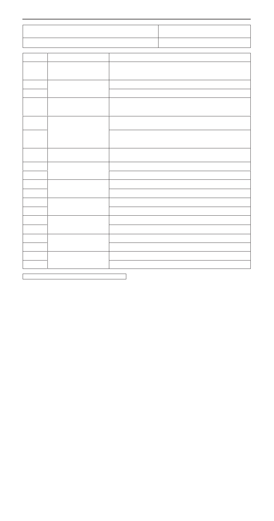
Code No.14, 15, 16, 17, 31, 32, 45, 51, 52, 54, 55, 56, 57, 58,
59, 73, 74, 83, 84 System inside SRS-ECU

Probable cause

These diagnostic trouble codes are output when a fault is detected in the SRS-ECU.
The defective parts and trouble causes for each diagnosis code No. are as follows.

D

Malfunction of SRS-ECU

Code No.

Defective parts

Trouble causes

14

Analog G-sensor

D

Analog G-sensor is not operating

D

Analog G-sensor characteristics are abnormal

D

Analog G-sensor output is abnormal

15

Front impact safing G-sensor

D

Short circuit in the safing G-sensor

16

D

Open circuit in the safing G-sensor

17

Side impact safing G-sensor

D

Safing G sensor is not operating

D

Safing G sensor characteristics are abnormal

D

Safing G sensor output is abnormal

31

Capacitor

D

Voltage at the capacitor terminal is higher than the specified value
for five seconds or more

32

D

Voltage at the capacitor terminal is lower than the specified value
for five seconds or more (this is not detected if diagnosis code
No.41 or 42 indicating battery voltage drop has been output.)

45

Non-volatile memory (EE-
PROM)

D

Non-volatile memory (EEPROM) is abnormal

51

Driver’s side air bag module
(squib ignition drive circuit)

D

Short circuit in the squib ignition drive circuit

52

(squib ignition drive circuit)

D

Open circuit in the squib ignition drive circuit

54

Front passenger’s side air
bag module (squib ignition

D

Short circuit in the squib ignition drive circuit

55

bag module (squib ignition
drive circuit)

D

Open circuit in the squib ignition drive circuit

56

Driver’s side pre-tensioner
(squib ignition drive circuit)

D

Short circuit in the squib ignition drive circuit

57

(squib ignition drive circuit)

D

Open circuit in the squib ignition drive circuit

58

Front passenger’s side pre-
tensioner (squib ignition drive

D

Short circuit in the squib ignition drive circuit

59

tensioner (squib ignition drive
circuit)

D

Open circuit in the squib ignition drive circuit

73

Side air bag module (R.H.)
(squib ignition drive circuit)

D

Short circuit in the squib ignition drive circuit

74

(squib ignition drive circuit)

D

Open circuit in the squib ignition drive circuit

83

Side air bag module (R.H.)
(squib ignition drive circuit)

D

Short circuit in the squib ignition drive circuit

84

(squib ignition drive circuit)

D

Open circuit in the squib ignition drive circuit

Replace the SRS-ECU.

SRS – 

Troubleshooting

52B-12

Code No.21, 22, 61, 62 
Driver’s air bag module (squib) system

Probable cause

Abnormal resistance is present between input terminals of driver’s air bag module
(squib). See table below for what each code tells.
However, once trouble is extinguished, SRS-warning lamp will go out. (Diagnosis
code will remain stored)

D

Malfunction of clock spring

D

Partially open as clock spring is not in neutral position

D

Defective wiring harnesses or connectors

D

Malfunction of driver’s air bag module (squib)

D

Malfunction of SRS-ECU

Code No.

Trouble causes

21

D

Short in driver’s air bag module (squib) or harness short

D

Short in clock spring

D

Defective connector*

22

D

Open in driver’s side air bag module (squib) or open harness

D

Open in clock spring

D

Disconnected driver’s air bag module (squib) connector

D

Partially open as clock spring is not in neutral position

D

Poor connector contact*

61

D

Driver’s air bag module (squib) harness shorted to power supply

62

D

Driver’s air bag module (squib) harness short to the earth

NOTE
*:

The shorting bars, which short positive (+) and negative (–) wires to prevent the air bags from accidental deployment
during the disconnection of the connector, are set in the squib circuit connectors. In a defective connector, the short-bar
may be still working  even after the  connection of the connector.

Check the following connectors: C-32, C-65

Repair

OK

Check trouble symptoms.

NG

Check wiring harness between clock spring and SRS-ECU.

Repair

OK

Replace SRS-ECU.

NO

Check clock spring. (Refer to P.52B-42.)

NG

Replace

NG

NG

Replace driver’s air bag module (squib).

SRS check harness
(MB991613)

Instrument panel
wiring harness
connector (2-pin)

Check harness

MUT-

II

 Self-diag code

D

Connect clock spring connector No.1 C-65 and the harness side connector
(2-pin).

D

Remove the cover from the No. 2 connector of the clock spring, and
then insert the probes (MB991222) and connect check harness to the
probe.

Caution
Never insert the probe directly to the terminals from the front of
the connector.

D

Disconnect the resistance connector from the SRS check harness
(MB991613) and connect to the check harness.

D

Connect the negative (–) battery terminal.

D

Erase diagnosis code memory.

Is code Nos.21, 22, 61 or 62 displayed?

Resistance (3 

)

2

1

YES

NO

Resistance (3 

)

Check harness

Probe
(MB991222)

Cover

2

SRS – 

Troubleshooting

52B-13

Code No.24, 25, 64, 65 
Front passenger’s air bag module (squib) system

Probable cause

Abnormal resistance is present between input terminals of front passenger’s air
bag module (squib). See table below for what each code tells.
However, once trouble is extinguished, SRS-warning lamp will go out. (Diagnosis
code will remain stored)

D

Defective wiring harnesses or connectors

D

Malfunction of front passenger’s air bag module
(squib)

D

Malfunction of SRS-ECU

Code No.

Trouble causes

24

D

Short in front passenger’s air bag module (squib) or short harness

25

D

Open in front passenger’s air bag module (squib) or open harness

D

Poor connector contact*

64

D

Short-circuit in front passenger’s air bag module (squib) harness to power supply

65

D

Short-circuit in front passenger’s air bag module (squib) harness to earth

NOTE
*:

The shorting bars, which short positive (+) and negative (–) wires to prevent the air bags from accidental deployment
during the disconnection of the connector, are set in the squib circuit connectors. In a defective connector, the short-bar
may be still working  even after the  connection of the connector.

NO

YES

Replace the front passenger’s air bag module (squib).

OK

Check trouble symptoms.

NG

Repair

OK

Replace SRS-ECU.

NG

Check wiring harness  between the front passenger’s air bag
module and SRS-ECU.

NG

Repair

SRS check harness (MB991613)

Instrument panel wiring harness

Front passenger’s  air bag
module connector

MUT-

II

 Self-diag code

D

Disconnect front passenger’s  air bag module connector C-15,
and connect the harness side connector to SRS check
harness (MB991613) connector No.1.

D

Connect negative (–) battery terminal.

D

Erase diagnosis code memory.

Is code Nos.24, 25, 64 or 65 output?

Resistance (3 

)

1

Check the following connectors: C-15, C-32

SRS – 

Troubleshooting

52B-14

Code No.26, 27, 66 or 67 Driver’s side pre-tensioner (squib)
system

Probable cause

These diagnosis codes are output if there is abnormal resistance between the input
terminals of the driver’s side pre-tensioner (squib).
The trouble causes for each diagnosis code No. are as follows.

D

Malfunction of wiring harnesses or connectors

D

Malfunction of driver’s side pre-tensioner (squib)

D

Malfunction of SRS-ECU

Code No.

Trouble causes

26

D

Short in driver’s side pre-tensioner (squib) or harness short

27

D

Open circuit in driver’s side pre-tensioner (squib) or open harness

D

Malfunction of connector contact

66

D

Short in driver’s side pre-tensioner (squib) harness leading to the power supply

67

D

Short in driver’s side pre-tensioner (squib) harness leading to the earth

Check the following connectors: D-36, D-41 <L.H. drive
vehicles>, D-38 <R.H. drive vehicles>

Repair

OK

Check trouble symptoms.

NG

Check wiring harness between the driver’s side pre-tensioner and
SRS-ECU.

Repair

OK

Replace SRS-ECU.

NG

NG

Replace the driver’s side pre-tensioner.

SRS check harness
(MB991613)

Check harness

MUT-

II

 Self-diag code

D

Disconnect the driver’s side pre-tensioner connector D-41 <L.H. drive
vehicles>, D-38 <R.H. drive vehicles>

D

Insert the probe (MB991222) from the rear of the harness side connector
and connect the check harness to the probe.

Caution
Never insert the probe directly to the terminals from the front of
the connector.

D

Disconnect the resistance connector from the SRS check harness
(MB991613) and connect to the check harness.

D

Connect the negative (–) battery terminal.

D

Erase diagnosis code memory.

Is code No.26, 27, 66 or 67 displayed?

Resistance (3 

)

YES

NO

Resistance (3 

)

Check harness

Probe
(MB991222)

Body wiring harness


Content   ..  306  307  308  309   ..