Mitsubishi Pajero Pinin. Manual - part 235


  Index      Mitsubishi     Mitsubishi Pajero Pinin - service repair manual 2001 year


Search            


Content   ..  233  234  235  236   ..


Mitsubishi Pajero Pinin. Manual - part 235


BASIC BRAKE SYSTEM – 

On-vehicle Service

35A-8

3.

With the engine running, step on the brake pedal and
then stop the engine.
Hold the pedal depressed for 30 seconds. If the pedal
height does not change, the booster is in good condition.
If the pedal rises, the booster is defective.

If the above three tests are okay, the booster performance
can be determined as good.
If one of the above three tests is not okay at least, the check
valve, vacuum hose, or booster will be defective.

CHECK VALVE OPERATION CHECK

1.

Remove the vacuum hose. (Refer to P.35A-15, 16.)

Caution
The check valve should not be disassembled from
the vacuum hose as they are united as one part.

2.

Check the operation of the check valve by using a vacuum
pump.

Vacuum pump
connection

Accept/reject criteria

Connection at the brake
booster side (A)

A negative pressure (vacuum) is
created and held.

Connection at the intake
manifold side (B)

A negative pressure (vacuum) is
not created.

Caution
If the check valve is defective, always replace it as
an assembly unit together with the vacuum hose.

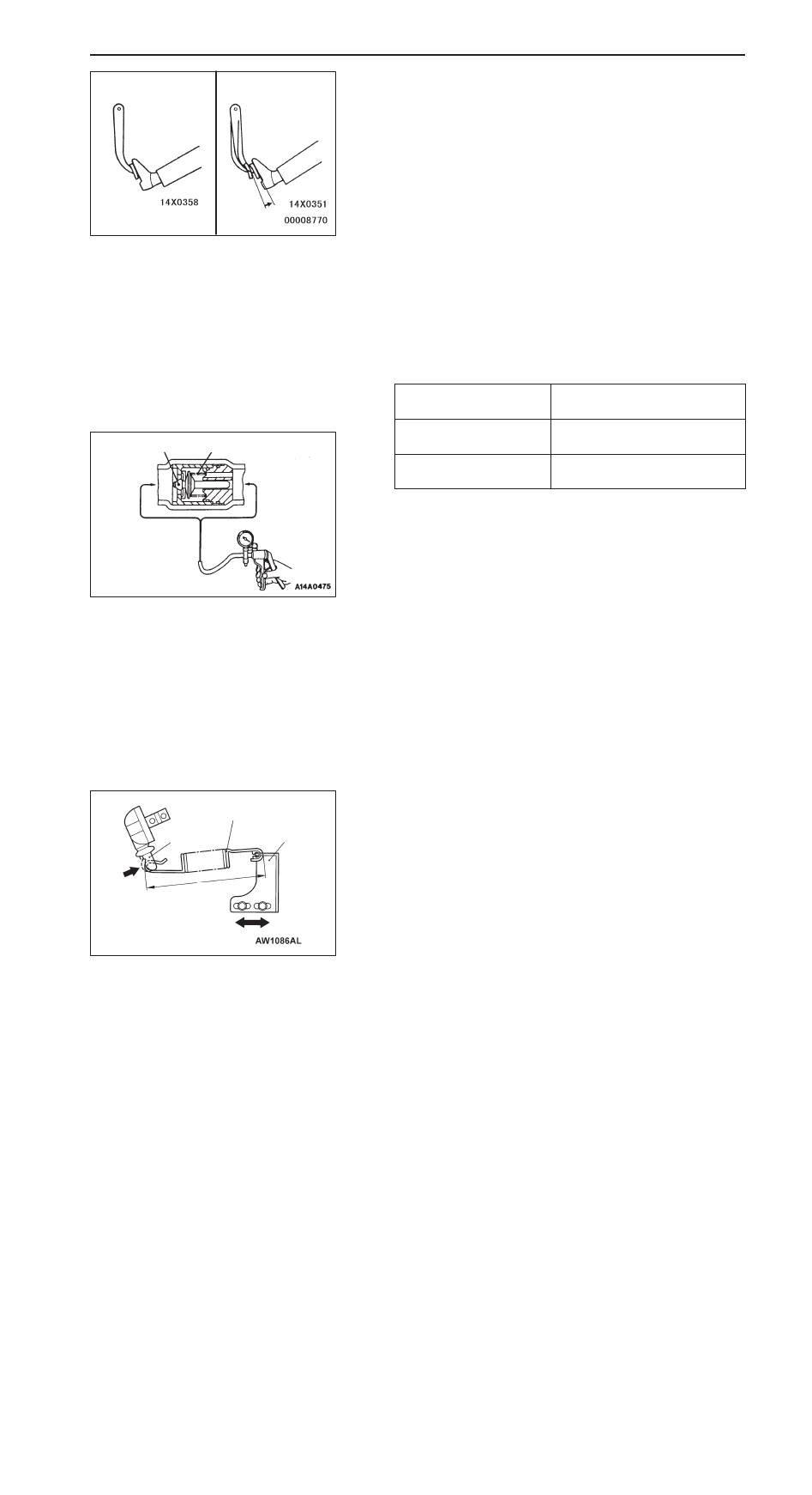
LOAD SENSING SPRING LENGTH CHECK
AND ADJUSTMENT

1.

Park the vehicle on a level ground. The vehicle should
be unloaded and supported only by wheels.

Caution
Never support the vehicle with jacks or other similar
means.

2.

With the lever pressed all the way to the load sensing
proportioning valve side, check whether or not the length
(shown in the figure) of the spring (the length between
its ends) is the standard value.

Standard value (A): 194 – 198 mm

3.

If the spring length is not within the standard value, loosen
the bolt attaching the support and adjust the distance by
moving the support.

Good

No  good

Valve

Spring

Booster
side

A

B

Intake
manifold
side

Load sensing spring

Spring support

Lever

A

BASIC BRAKE SYSTEM – 

On-vehicle Service

35A-9

LOAD SENSING PROPORTIONING VALVE
FUNCTION TEST

1.

Connect pressure gauges to the input and output ports
of the load sensing proportioning valve.

2.

Bleed the system. (Refer to P.35A-10.)

3.

Disconnect the spring at the support side.

4.

Place the spring so that it is in parallel with the load sensing
proportioning valve, and then pull in the direction indicated
by arrow A so that its length H shown in the figure (the
length between its ends) is as noted below.

NOTE
At this time the lever is pressed all the way to the load
sensing proportioning valve side.

5.

Check at this time whether or not the output fluid’s pressure,
relative to the load sensing proportioning valve’s input fluid
pressure, is within the standard value.

Standard value:

Spring length 
H mm

Input fluid
pressure MPa

Output fluid pressure
MPa

199*

1

9.8

4.2 – 6.0

217*

2

9.8

9.7 – 10.5

16.7

14.5 – 16.3

NOTE

*

1

 and 

*

2


indicate the applicable lengths for unladen

and laden vehicles respectively.

6.

Measure each output fluid pressure at both valves, and
check that the difference between the two is at the limit
value or less.

Limit: 0.39 MPa

7.

After making the check, install the spring. Disconnect the
pressure gauges from the load sensing proportioning valve
and bleed air.

Pressure gauge

Load sensing pro-
portioning valve

Lever

A

H

Load sensing spring

Load sensing pro-
portioning valve

Parallel

BASIC BRAKE SYSTEM – 

On-vehicle Service

35A-10

BLEEDING

Caution

Specified brake fluid: DOT3 or DOT4
Always use the specified brake fluid. Avoid using a mixture
of the specified brake fluid and other fluid.

MASTER CYLINDER BLEEDING

The master cylinder used has no check valve, so if bleeding
is carried out by the following procedure, bleeding of air from
the brake pipeline will become easier. (When brake fluid is
not contained in the master cylinder.)
1.

Fill the reserve tank with brake fluid.

2.

Keep the brake pedal depressed.

3.

Have another person cover the master cylinder outlet with
a finger.

4.

With the outlet still closed, release the brake pedal.

5.

Repeat steps 2 – 4 three or four times to fill the inside
of the master cylinder with brake fluid.

BRAKE PIPE LINE BLEEDING

Bleed the air in the sequence shown in the figure.

BRAKE FLUID LEVEL SENSOR CHECK

The brake fluid level sensor is in good condition if there is
no continuity when the float surface is above “MIN” and if
there is continuity when the float surface is below “MIN”.

(  ): R.H. drive vehicles

4 (2)

1 (3)

2 (4)

3 (1)

MAX

MIN

BASIC BRAKE SYSTEM – 

On-vehicle Service

35A-11

DISC BRAKE PAD CHECK AND REPLACEMENT

NOTE
The brake pads have wear indicators that contact the brake
disc when the brake pad thickness reaches approximately
2 mm and emit a squealing sound to warn the driver.

1.

Check the brake pad thickness through the caliper body
check port.

Standard value: 10.0 mm

Limit: 2.0 mm

2.

When the thickness is less than the limit, always replace
the pads at an axle set.

3.

Remove the guide lock pin bolt. Pivot the caliper assembly
and hold it with wires.

4.

Remove the following parts from the caliper support.
1.

Pad and wear indicator assembly

2.

Pad assembly

3.

Clip

4.

Inner shim

5.

Outer shim

5.

In order to measure the brake drag force after pad
installation, measure the rotary-sliding resistance of the
hub with the pads removed. (Refer to P.35A-20, 25.)

6.

Install the pads and caliper assembly, and then check
the brake drag force. (Refer to P.35A-21, 26.)

FRONT

REAR

4

2

5

3

1

3

3

1

4

3

2

5

FRONT

REAR


Content   ..  233  234  235  236   ..