Mitsubishi Lancer (4A9 engine). Manual - part 292


  Index      Mitsubishi     Mitsubishi Lancer (4A9 engine) 12GS41 & 44S - service repair manual


Search            


Content   ..  290  291  292  293   ..


Mitsubishi Lancer (4A9 engine). Manual - part 292


ACA00894

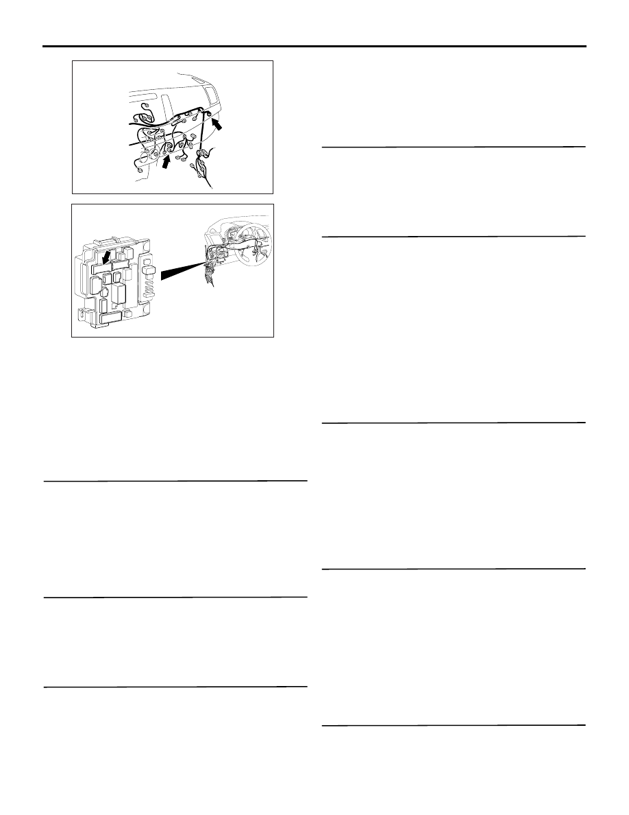
Connector: C-60,  C-150 <LHD>

AB

C-60 (B)

C-150 (GR)

AC612709

AU

Connector: C-317 <LHD>
ETACS-ECU

TROUBLESHOOTING

HEATER, AIR CONDITIONER AND VENTILATION

55A-49

COMMENTS ON TROUBLE SYMPTOM
If the heater control unit is not energised, the power 
supply or earth system to the ECU may be defective.

PROBABLE CAUSES

• Malfunction of the heater control unit

• Damaged wiring harness or connectors

DIAGNOSTIC PROCEDURE

STEP 1. M.U.T.-III other system's diagnosis code
Check that the ETACS-ECU has not set a diagnosis 
code.

Q: Is the diagnosis code set?

YES : 

Carry out the diagnosis code procedures . 

Refer to GROUP 54A, ETACS-ECU .

NO : 

Go to Step 2.

STEP 2. Connector check: C-60 heater control 
unit connector

Q: Is the check result normal?

YES : 

Go to Step 3.

NO : 

Repair the connector concerned.

STEP 3. Measure the voltage at the C-60 heater 
control unit connector.
(1) Disconnect the connector, and measure at the 

wiring harness side.

(2) Ignition switch: ON

(3) Voltage between terminal No. 15 and body earth

OK: System voltage

Q: Is the check result normal?

YES : 

Go to Step 6.

NO : 

Go to Step 4.

STEP 4. Connector check: C-317 ETACS-ECU 
connector

Q: Is the check result normal?

YES : 

Go to Step 5.

NO : 

Repair the connector concerned.

STEP 5. Check the wiring harness between C-60 
heater control unit connector terminal No. 15 and 
C-317 ETACS-ECU connector terminal No. 5.

• Check the power supply line for open circuit.

NOTE: Prior to the wiring harness inspection, check 
joint connector C-150, and repair if necessary.

Q: Is the check result normal?

YES : 

Intermittent malfunction (Refer to GROUP 

00 

− How to Use Troubleshooting/

Inspection Service Points - How to Cope 
with Intermittent Malfunction ).

NO : 

Repair the wiring harness.

STEP 6. Measure the voltage at the C-60 heater 
control unit connector.
(1) Disconnect the connector, and measure at the 

wiring harness side.

(2) Voltage between terminal No. 13 and body earth

OK: System voltage

Q: Is the check result normal?

YES : 

Go to Step 8.

NO : 

Go to Step 7.

STEP 7. Check the wiring harness between C-60 
heater control unit connector terminal No. 13 and 
C-317 ETACS-ECU connector terminal No. 10.

• Check the power supply line for open circuit.

Q: Is the check result normal?

YES : 

Intermittent malfunction (Refer to GROUP 

00 

− How to Use Troubleshooting/

Inspection Service Points - How to Cope 
with Intermittent Malfunction ).

NO : 

Repair the wiring harness.

STEP 8. Measure the resistance at the C-60 
heater control unit connector.
(1) Disconnect the connector, and measure at the 

wiring harness side.

TROUBLESHOOTING

HEATER, AIR CONDITIONER AND VENTILATION

55A-50

(2) Resistance between terminal No. 14 and body 

earth

OK: Continuity exists (2 

 or less)

Q: Is the check result normal?

YES : 

Replace the heater control unit.

NO : 

Go to Step 9.

STEP 9. Check the wiring harness between C-60 
heater control unit connector terminal No. 14 and 
body earth.

• Check the earth wires for open circuit.

Q: Is the check result normal?

YES : 

Intermittent malfunction (Refer to GROUP 

00 

− How to Use Troubleshooting/

Inspection Service Points - How to Cope 
with Intermittent Malfunction ).

NO : 

Repair the wiring harness.

TROUBLE SYMPTOM CHART <VEHICLES 
WITH A/C>

M1554005002629

Trouble symptom

Inspection 
procedure No.

Reference 
page

Communication with the M.U.T.-III is not possible

1

Cool air does not come

2

The blower does not work

3

The blower air volume cannot be changed

4

The inside/outside air changeover is impossible

5

The A/C compressor does not work <Petrol engine>

6

The A/C compressor does not work <Diesel engine>

7

The A/C indicator flashes

8

A/C outlet air temperature cannot be set

9

Air outlets changeover is impossible

10

A/C pressure sensor system

11

Blower motor power supply system

12

A/C-ECU power supply system

13

The PTC heater does not work <Vehicles with PTC heater>

14

The buzzer does not sound

15

(Refer to 
GROUP 54A 

− 

Combination 
Meter ).

SYMPTOM PROCEDURES

INSPECTION PROCEDURE 1: Communication with the M.U.T.-III is not possible.

COMMENTS ON TROUBLE SYMPTOM
If communication with all other systems is not possi-
ble, there is a high possibility that there is a malfunc-
tion of the diagnosis line. If only the A/C system can 
not communicate with the M.U.T.-III, the A/C-ECU 
may be defective.

PROBABLE CAUSE
Malfunction of the A/C-ECU

DIAGNOSIS PROCEDURE

STEP 1. M.U.T.-III CAN bus diagnostics
Use the M.U.T.-III to diagnose the CAN bus lines.

Q: Is the check result normal?

TROUBLESHOOTING

HEATER, AIR CONDITIONER AND VENTILATION

55A-51

YES : 

Check and repair the power supply circuit 

system.

NO : 

Repair the CAN bus line (Refer to GROUP 
54C, Troubleshooting ).

INSPECTION PROCEDURE 2: Cool air does not come

CIRCUIT OPERATION
If the blower air temperature can not be cool when 
turning A/C switch ON and lowering the preset tem-
perature, inadequate refrigerant quantity, sensors, 
harness or connectors may be suspected.

PROBABLE CAUSE
Damaged wiring harness or connectors

DIAGNOSIS PROCEDURE

STEP 1. Check the blower operation
Check that air blows through the air outlets.
(1) Turn the ignition switch to the ON position.
(2) Blower knob: Other than OFF
(3) Check that the air comes out of the blower.

Q: Is the check result normal?

YES : 

Go to Step 2.

NO : 

Refer to Inspection Procedure 3 "The 
blower does not work ".

STEP 2. Check the A/C compressor operation
Check that the compressor operates under the fol-
lowing conditions.

• Engine operation

• Air conditioner switch: ON

• Blower knob: Maximum air volume

• Temperature control dial: 18°C (MAX COOL)

NOTE: The compressor does not work when the 
blower intake temperature is 0

°

C or less.

Q: Is the check result normal?

YES : 

Go to Step 3.

NO : 

Refer to Inspection Procedure 6 "The A/C 
compressor does not work < Petrol engine> 
", Inspection Procedure 7 "The A/C 
compressor does not work <Diesel engine> 
".

STEP 3. M.U.T.-III CAN bus diagnostics
Use the M.U.T.-III to diagnose the CAN bus lines.

Q: Is the check result normal?

YES : 

Go to Step 4.

NO : 

Repair the CAN bus lines. (Refer to GROUP 
54C 

− Troubleshooting ).

STEP 4. M.U.T.-III diagnosis code
Check that the diagnosis code related to the air con-
ditioner is not set.

Q: Is the diagnosis code set?

YES : 

Carry out the diagnosis code procedures. 

Refer to .

NO : 

Go to Step 5.

STEP 5. Refrigerant level check
Check that the refrigerant level is adequate. Refer to 
.

Q: Is the check result normal?

YES : 

Intermittent malfunction (Refer to GROUP 

00, How to Cope with Intermittent 
Malfunction ).

NO : 

Charge or remove the refrigerant level. 
Refer to .

TROUBLESHOOTING

HEATER, AIR CONDITIONER AND VENTILATION

55A-52

INSPECTION PROCEDURE 3: The blower does not work

Blower Motor Circuit

FUSIBLE
LINK

37

BLOWER
RELAY

ETACS-
ECU 

A/C-ECU

BLOWER
MOTOR

POWER
TRANSISTOR

NOTE

: LHD
: RHD

Wire colour code 
B : Black     LG : Light green     G : Green     L : Blue     W : White     Y : Yellow     SB : Sky blue 
BR : Brown     O : Orange     GR : Grey     R : Red     P : Pink     V : Violet     PU : Purple     SI : Silver

FUSIBLE
LINK

42

<4N1>

<4A9, 4J1, 4B1>

ACB02688


Content   ..  290  291  292  293   ..