Mitsubishi Lancer (4A9 engine). Manual - part 175


  Index      Mitsubishi     Mitsubishi Lancer (4A9 engine) 12GS41 & 44S - service repair manual


Search            


Content   ..  173  174  175  176   ..


Mitsubishi Lancer (4A9 engine). Manual - part 175


MITSUBISHI MULTI COMMUNICATION SYSTEM (MMCS)

CHASSIS ELECTRICAL

54A-362

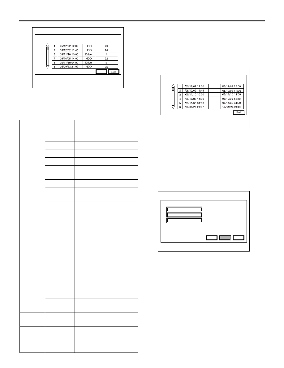
3. The logs are displayed from the latest one.
4. The log data is erased by pressing "Delete."
EACH LOG INFORMATION: FACTOR CODE 
TABLE

NOTE: 

*1

: The log is displayed when the number of 

speakers is unexpected.

*2

: The log is displayed when the vehicle model is 

unexpected.

Time Adjustment Log

5. Select "Time Adjustment Log" on the "Versions 

Log Information" screen.

6. The time adjustment logs are displayed.
As for Factor, the following two types are displayed.
CT: Automatic adjustment
MAN: Manual adjustment

TOUCH SWITCH CONFIRMATION

1. Select "Touch Switch Confirmation" on "Service" 

screen.

Item

Factor 
number

Produced log

Drive

20

Log concerning focus

21

Log concerning disc type

22

Log concerning disc

25

Log concerning SEEK

26

Log concerning servo 
start-up

27

Log concerning power-On

28

Log concerning loading / 
eject operation

29

Log concerning pick-up 
operation

30

Log concerning state of 
mechanism

52

Log concerning TOC 
reading

HDD

1

Log concerning high 
temperature

2

Log concerning low 
temperature

Monitor

1

Log concerning high 
temperature

AMP

0

Log concerning 
connection

15

Log concerning 
communication

SP

*1

1,2,4,8

Log concerning number of 
speakers unexpected

CAR

*2

0 -12,     
128 -131, 
133,160, 
192,255

Log concerning vehicle 
model unexpected

AC611721

Service Data Log

Time

Item

Factor

Delete

AC

AC611720

Time Adjustment Information

After

Factor

Before

CT

CT

CT

CT

CT

CT

AC

Service

TMC Sensitivity

Versions Log Information

Touch Switch Confirmation

2/2

Back

Next

Previous

AC903642

AB

MITSUBISHI MULTI COMMUNICATION SYSTEM (MMCS)

CHASSIS ELECTRICAL

54A-363

2. If you touch the screen, the colour of the dotted 

coordinate at the touched area will be changed.

DIAGNOSIS CODE CHART <VEHICLES 
FOR RUSSIA>

M1546001700498

CAUTION

On troubleshooting, if the ignition switch is 
turned ON while disconnecting connector(s), 
diagnosis code(s) associated with other system 
may be set. On completion, confirm all systems 
for diagnosis code(s). If diagnosis code(s) are 
set, erase them all.

DIAGNOSIS CODE PROCEDURES 
<VEHICLES FOR RUSSIA>

Code No.B2226: AND [Audio visual navigation (HDD) unit] error

CAUTION

Whenever the ECU is replaced, ensure that the 
power supply circuit and the earthing circuit are 
normal. (Check that the voltage is 10 V or more.)
TROUBLE JUDGEMENT
When the CAN box unit receives the signal that an 

abnormality (service data) occurs to the multivision 
display, the CAN box unit sets diagnosis code 
B2226.

PROBABLE CAUSES

• The multivision display may be defective

• The CAN box unit may be defective

If you complete the touch switch confirmation.

please push [MENU]

AC606337

AC505342

Diagnosis 
code No.

Description

Reference 
page

B2226

AND [Audio Visual Navigation (HDD) unit] error

B2240

Communication error with CAN Box (Communication error between CAN box 
unit and multivision display)

B2477

Chassis No. Not Programmed

U0019

Bus off (CAN-B)

U0141

ETACS CAN timeout

U0151

SRS-ABG CAN timeout

U0155

Meter CAN timeout

U0164

A/C-ECU CAN timeout

U0168

WCM/KOS CAN timeout

U1415

Coding not completed/Data fail

U1417

Implausible coding data

MITSUBISHI MULTI COMMUNICATION SYSTEM (MMCS)

CHASSIS ELECTRICAL

54A-364

DIAGNOSIS PROCEDURE

STEP 1. M.U.T.-III CAN bus diagnostics
Use the M.U.T.-III to diagnose the CAN bus lines.

Q: Is the check result normal?

YES : 

Go to Step 2.

NO : 

Repair the CAN bus line.

STEP 2.Check that the multivision display 
operate.
Check that the multivision display work normally.
NOTE: Check that there is no writing of service data 
log on the "Versions Log Information" for the MMCS 
service mode.(Refer to .)

Q: Is the check result normal?

YES : 

Go to Step 3.

NO : 

Diagnose the multivision display (Refer to 
Trouble symptom chart ).

STEP 3. Check whether the diagnosis code is 
reset.
Check again if the diagnosis code is set to the CAN 
box unit.
(1) Erase the diagnosis code.

(2) Turn the ignition switch from "LOCK" (OFF) 

position to "ON" position.

(3) Check if diagnosis code is set.

Q: Is the diagnosis code set?

YES : 

Replace the CAN box unit temporarily and 

go to Step 4.

NO : 

The diagnosis is complete.

STEP 4. Check whether the diagnosis code is 
reset.
After temporary replacement of the multivision dis-
play, check if diagnosis code is set to the CAN box 
unit.
(1) Erase the diagnosis code.
(2) Turn the ignition switch from "LOCK" (OFF) 

position to "ON" position.

(3) Check if diagnosis code is set.
(4) Turn the ignition switch to the "LOCK" (OFF) 

position.

Q: Is the diagnosis code set?

YES : 

Replace the multivision display.

NO : 

Replace the CAN box unit.

Code No.B2240 Communication error with CAN box (Communication error between CAN box unit and 
multivision display)

CAUTION

• If the diagnosis code No. B2240 is set, be sure to diagnose the CAN bus line.
• Before replacing the CAN box unit, ensure that the power supply circuit, the earth circuit, and the 

communication circuit are normal. (Check that the voltage is 10 V or more.)

CAN Box Unit Communication Circuit

MULTIVISION DISPLAY

CAN BOX UNIT

Wire colour code 
B : Black     LG : Light green     G : Green     L : Blue     W : White     Y : Yellow     SB : Sky blue 
BR : Brown     O : Orange     GR : Grey     R : Red     P : Pink     V : Violet     PU : Purple     SI : Silver

MITSUBISHI MULTI COMMUNICATION SYSTEM (MMCS)

CHASSIS ELECTRICAL

54A-365

TROUBLE JUDGEMENT
When the abnormality occurs in the transmission/
reception data between the CAN box unit and multiv-
ision display, the CAN box unit sets diagnosis code 
B2240.

PROBABLE CAUSES

• Malfunction of multivision display

• Malfunction of CAN box unit malfunction

• Damaged wiring harness and connectors

DIAGNOSIS PROCEDURE

STEP 1. Confirmation in MMCS service mode
Perform "Network/Connect Line Check" of the 
MMCS service mode, and check that the communi-
cation between the CAN box unit and the multivision 
display is normal. (Refer to .)
NOTE: When the communication between the CAN 
box unit and the multivision display is normal, "CAN 
BOX" is displayed on the check result screen. How-
ever, if the communication is not possible, "CAN 
BOX" is not displayed.

Q: Is the check result normal?

YES : 

Go to Step 2.

NO : 

Go to Step 3.

STEP 2. M.U.T.-III CAN bus diagnostics
Use the M.U.T.-III to diagnose the CAN bus lines.

Q: Is the check result normal?

YES : 

Go to Step 3.

NO : 

Repair the CAN bus line (Refer to GROUP 
54C 

− Troubleshooting ).

STEP 3. Connector check: C-142 multivision 
display connector and C-54 CAN box unit

Q: Is the check result normal?

YES : 

Go to Step 4.

NO : 

Repair or replace the damaged 
component(s).

STEP 4. Check the wiring harness between C-142 
multivision display connector terminal No.43, 59, 
58 and C-54 CAN box unit connector terminal 
No.5, 4, 6.
Check the communication lines for open circuit or 
short circuit.

Q: Is the check result normal?

YES : 

Go to Step 5.

NO : 

Repair the wiring harness.

STEP 5. Check whether the diagnosis code is 
reset.
Check again if the diagnosis code is set to the CAN 
box unit.
(1) Erase the diagnosis code.
(2) Turn the ignition switch from "LOCK" (OFF) 

position to "ON" position.

(3) Check if diagnosis code is set.

Q: Is the diagnosis code set?

YES : 

Replace the CAN box unit temporarily and 

go to Step 6.

NO : 

The diagnosis is complete.

STEP 6. Check whether the diagnosis code is 
reset.
Check again if the diagnosis code is set to the CAN 
box unit.
(1) Erase the diagnosis code.
(2) Turn the ignition switch from "LOCK" (OFF) 

position to "ON" position.

(3) Check if diagnosis code is set.

Q: Is the diagnosis code set?

YES : 

Replace the multivision display.

NO : 

Replace the CAN box unit.

AC701094

Connectors: C-54, C-142 <LHD>

AO

C-54

C-142 (GR)

AC701122 BA

C-54

Connectors: C-54, C-142 <RHD>

C-142 (GR)


Content   ..  173  174  175  176   ..