Mitsubishi Evolution X. Manual - part 568
 

  Index      Mitsubishi     Mitsubishi Evolution X - service repair manual 2008 year


Search            


Content   ..  566  567  568  569   ..


Mitsubishi Evolution X. Manual - part 568


DIAGNOSIS

TSB Revision

KEYLESS OPERATION SYSTEM (KOS)

42B-179

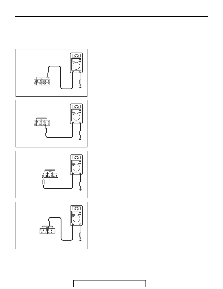
STEP 9. Check the wiring harness between the receiver 
antenna assembly connector D-14 (terminal Nos.1, 8, 12, 3, 
5) and the ground for short circuit.
(1) Disconnect reciever anntena assembly connector D-14, 

and check the wiring harness.

(2) Check the wiring harness between reciever anntena 

assembly connector D-14 (terminal No.1) and ground

OK: No continuity

(3) Check the wiring harness between reciever anntena 

assembly connector D-14 (terminal No.8) and and ground

OK: No continuity

(4) Check the wiring harness between reciever anntena 

assembly connector D-14 (terminal No.12) and and ground

OK: No continuity

(5) Check the wiring harness between reciever anntena 

assembly connector D-14 (terminal No.3) and ground

OK: No continuity

AC709707FZ

Harness side: D-14

AC709707FY

Harness side: D-14

AC709707FX

Harness side: D-14

AC709707FW

Harness side: D-14

DIAGNOSIS

TSB Revision

KEYLESS OPERATION SYSTEM (KOS)

42B-180

(6) Check the wiring harness between reciever anntena 

assembly connector D-14 (terminal No.5) and ground

OK: No continuity

Q: Is the wiring harness between receiver antenna 

assembly connector D-14 (terminal Nos.1, 8, 12, 3, 5) 
and the ground in good condition?
YES  : 
Go to Step 10.
NO (receiver antenna assembly connector D-14 terminal 
No.1  

 ground.) : Repair the wiring harness between 

receiver antenna assembly connector D-14  (terminal 
No.1) and the KOS-ECU connector C-05 (terminal 
No.12).

NO (receiver antenna assembly connector D-14 terminal 
No.8 

 ground.) : Repair the wiring harness between 

receiver antenna assembly connector D-14  (terminal 
No.8) and the ground.

NO (receiver antenna assembly connector D-14 terminal 
No.12 

 ground.) : Repair the wiring harness between 

receiver antenna assembly connector D-14  (terminal 
No.12) and the ground.

NO (receiver antenna assembly connector D-14 terminal 
No.3 

 ground.) : Repair the wiring harness between 

receiver antenna assembly connector D-14  (terminal 
No.3) and the ground.

NO (receiver antenna assembly connector D-14 terminal 
No.5 

 ground.) : Repair the wiring harness between 

receiver antenna assembly connector D-14  (terminal 
No.5) and the ground.

STEP 10. Replace the receiver antenna assembly, and 
retest the system.
Check that the keyless operation key can be registered.
Q: Is the keyless operation key that cannot be registered 

using scan tool?
YES : 
Go to Step 11.
NO :  The procedure is complete.

AC709707FV

Harness side: D-14

DIAGNOSIS

TSB Revision

KEYLESS OPERATION SYSTEM (KOS)

42B-181

STEP 11. Check the wiring harness between the receiver 
antenna module connector C-08 (terminal Nos. 2, 1, 8, 12) 
and the KOS-ECU connector C-05 (terminal Nos. 11, 12, 32, 
7) for open circuit.
(1) Disconnect reciever anntena module connector C-08 and 

KOS-ECU connector C-05, and check the wiring harness.

(2) Check the wiring harness between reciever anntena 

module connector C-08 (terminal No.2) and KOS-ECU 
connector C-05 (terminal No.11)

OK: Continuity exists (2 

 or less)

(3) Check the wiring harness between reciever anntena 

module connector C-08 (terminal No.1) and KOS-ECU 
connector C-05 (terminal No.12)

OK: Continuity exists (2 

 or less)

(4) Check the wiring harness between reciever anntena 

module connector C-08 (terminal No.8) and KOS-ECU 
connector C-05 (terminal No.32)

OK: Continuity exists (2 

 or less)

AC709707

Harness side: C-05

DZ

Harness side: C-08

AC709707

Harness side: C-05

DZ

Harness side: C-08

AC709707

Harness side: C-05

EB

Harness side: C-08

DIAGNOSIS

TSB Revision

KEYLESS OPERATION SYSTEM (KOS)

42B-182

(5) Check the wiring harness between reciever anntena 

module connector C-08 (terminal No.12) and KOS-ECU 
connector C-05 (terminal No.7)

OK: Continuity exists (2 

 or less)

Q: Is the wiring harness between receiver antenna module 

connector C-08 (terminal Nos. 2, 1, 8, 12) and the 
KOS-ECU connector C-05 (terminal Nos. 11, 12, 32, 7) in 
good condition?
YES  : 
Go to Step 12.
NO (receiver antenna module connector C-08 terminal 
No.2 

 KOS-ECU connector C-05 terminal No.11.) : 

Repair the wiring harness between receiver antenna 
module connector C-08  (terminal No. 2) and the 
KOS-ECU connector C-05 (terminal No. 11).

NO (receiver antenna module connector C-08 terminal 
No.1 

 KOS-ECU connector C-05 terminal No.12.) : 

Repair the wiring harness between receiver antenna 
module connector C-08  (terminal No. 1) and the 
KOS-ECU connector C-05 (terminal No. 12).

NO (receiver antenna module connector C-08 terminal 
No.8 

 KOS-ECU connector C-05 terminal No.32.) : 

Repair the wiring harness between receiver antenna 
module connector C-08  (terminal No. 8) and the 
KOS-ECU connector C-05 (terminal No. 32).

NO (receiver antenna module connector C-08 terminal 
No.12 

 KOS-ECU connector C-05 terminal No.7.) : 

Repair the wiring harness between receiver antenna 
module connector C-08  (terminal No. 12) and the 
KOS-ECU connector C-05 (terminal No. 7).

AC709707EC

Harness side: C-08

Harness side: C-05


Content   ..  566  567  568  569   ..