Mitsubishi Lancer Evolution X. Manual - part 297


  Index      Mitsubishi     Mitsubishi Lancer Evolution X GS41EVO - service repair manual 2008 year


Search            


Content   ..  295  296  297  298   ..


Mitsubishi Lancer Evolution X. Manual - part 297


MULTIPORT FUEL INJECTION (MFI) DIAGNOSIS

TSB Revision

MULTIPORT FUEL INJECTION (MFI)

13A-253

STEP 12. Check for short circuit to ground and harness 
damage between heated oxygen sensor (rear) connector 
D-35 (terminal No. 3) and ECM connector B-09 (terminal 
No. 40).
NOTE: Check harness after checking intermediate connectors 
A-13 and C-45. If intermediate connectors are damaged, repair 
or replace them. Refer to GROUP 00E, Harness Connector 
Inspectio

P.00E-2

. Then go to Step 14.

Q: Is the harness wire in good condition?

YES : Go to Step 13.
NO :  Repair it. Then go to Step 14.

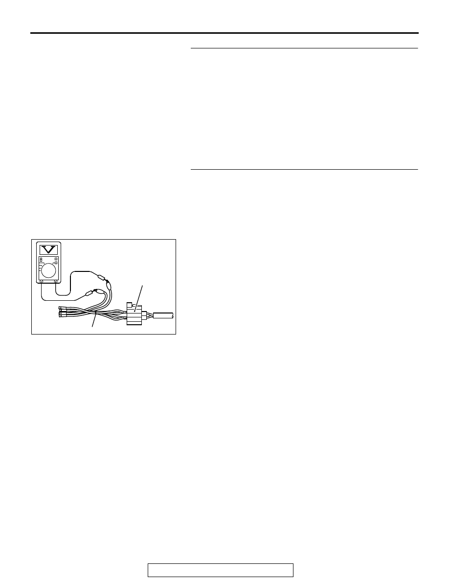
STEP 13. Check the heated oxygen sensor (rear).
(1) Disconnect the heated oxygen sensor (rear) connector 

D-35 and connect test harness special tool MB991658 to 
the connector on the heated oxygen sensor (rear) side.

(2) Warm up the engine until engine coolant temperature 

reaches 80° C (176° F) or higher.

(3) Drive at 50 km/h (31mph) or more for 10 minutes.
(4) Connect a digital voltage meter between terminal No. 3 and 

terminal No. 4.

(5) Measure the output voltage of heated oxygen sensor under 

the following driving.

• Transaxle: 2nd speed
• Drive with wide open throttle
• Engine: 3,500 r/min or more

Standard value: 0.6  1.0 V

NOTE: If the temperature of sensing area does not reach 
the high temperature [of approximately 400

°

C (752

°

F) or 

more] even though the heated oxygen sensor is normal, the 
output voltage would be possibly low in spite of the rich 
air/fuel ratio.
NOTE: When the vehicle is driven with high loads, the tem-
perature of the sensing area of the heated oxygen sensor is 
sufficiently high. Thus, it is not necessary to apply the volt-
age to the heater.

Q: Is the measured voltage between 0.6 and 1.0 volt?

YES : Replace the ECM. When the ECM is replaced, 

register the ID code. Refer to GROUP 42B, ID Code 
Registration Necessity Judgment Table <Vehicles 
with KOS> 

P.42B-11

 or GROUP 42C, ID Codes 

Registration Judgment Table <Vehicles with WCM> 

P.42C-9

. Then go to Step 14.

NO :  Replace the heated oxygen sensor (rear). Then go to 

Step 14.

AK604493AB

MB991658

Heated oxygen
sensor component
side connector

MULTIPORT FUEL INJECTION (MFI) DIAGNOSIS

TSB Revision

MULTIPORT FUEL INJECTION (MFI)

13A-254

STEP 14. Test the OBD-II drive cycle.
(1) Carry out a test drive with the drive cycle pattern. Refer to 

Diagnostic Function − OBD-II Drive Cycle − Pattern 22 

P.13A-9

.

(2) Check the diagnostic trouble code (DTC).
Q: Is DTC P0137 set?

YES : Retry the troubleshooting.
NO :  The inspection is complete.

DTC P0138: Heated Oxygen Sensor (rear) Circuit High Voltage

AK704250

1 2
3 4

1

2

3 4 5 6 7 8 9 10 11 12 13 14 15 16

17 18 19 20 21 22 23 24 25 26 27 28 29 30 31 32

33 34 35 36 37 38 39 40 41 42 43 44 45 46 47 48

49 50 51 52 53 54 55 56 57 58 59 60 61 62 63 64

2

8

7

6

5

4

3

11

21

20

19

18

17

16

15

14

13

12

9

22

1

10

1

2

3 4 5 6

AB

D-35

FROM MFI RELAY

TO ECM

1

4

2

3

HEATED OXYGEN SENSOR (REAR) CIRCUIT

HEATED OXYGEN
SENSOR (REAR)

B-09

YELLO

W

ORANGE

ORANGE

YELLO

W

ENGINE
CONTROL
MODULE

0.5 V

C-45

3

41

40

2

ORANGE

YELLO

W

6

5

A-13

MULTIPORT FUEL INJECTION (MFI) DIAGNOSIS

TSB Revision

MULTIPORT FUEL INJECTION (MFI)

13A-255

.

CIRCUIT OPERATION

• A voltage corresponding to the oxygen concen-

tration in the exhaust gas is sent to the ECM (ter-
minal No. 40) from the output terminal (terminal 
No. 3) of the heated oxygen sensor (rear).

• Terminal No. 4 of the heated oxygen sensor 

(rear) is grounded with ECM (terminal No. 41).

• The ECM applies an offset voltage of 0.5 volt to 

terminal No. 4 of the heated oxygen sensor 
(rear).

.

TECHNICAL DESCRIPTION

• The output signal of the heated oxygen sensor 

(front) is compensated by the output signal of the 
heated oxygen sensor (rear).

• The ECM checks for the heated oxygen sensor 

(rear) output voltage.

.

DESCRIPTIONS OF MONITOR METHODS

Heated oxygen sensor (rear) output voltage is over 

specified range.

.

MONITOR EXECUTION

Continuous

.

MONITOR EXECUTION CONDITIONS 
(Other monitor and Sensor)

Other Monitor (There is no temporary DTC stored 

in memory for the item monitored below)

• Heated oxygen sensor (front) monitor
• Heated oxygen sensor (front) heater monitor
• Heated oxygen sensor (rear) heater monitor
• Heated oxygen sensor (front) inactive monitor
• Heated oxygen sensor offset voltage monitor
• Air/fuel ratio feedback monitor

Sensor (The sensor below is determined to be 

normal)

• Mass airflow sensor
• Engine coolant temperature sensor
• Intake air temperature sensor
• Barometric pressure sensor

.

AK704229AB

Connector: A-13

A-13

AK704227

Connector: B-09

ECM

B-09 (GR)

AB

AK704251

Connector: C-45

C-45

AB

AK704232

Heated oxygen
sensor (rear)

Connector: D-35

D-35 (B)

AB

Rear heater
duct

MULTIPORT FUEL INJECTION (MFI) DIAGNOSIS

TSB Revision

MULTIPORT FUEL INJECTION (MFI)

13A-256

DTC SET CONDITIONS
Logic Flow Chart

.

Check Conditions

• 2 seconds or more have passed since the engine 

starting sequence was completed.

• Heated oxygen sensor offset voltage is between 

0.4 and 0.6 volt.

Judgement Criterion

• Heated oxygen sensor (rear) output voltage has 

continued to be 1.8 volts or higher for 2 seconds.

.

FAIL-SAFE AND BACKUP FUNCTION

• None

.

OBD-II DRIVE CYCLE PATTERN

Refer to Diagnostic Function − OBD-II Drive Cycle − 

Pattern 23 

P.13A-9

.

.

TROUBLESHOOTING HINTS (The most 
likely causes for this code to be set are:)

• Short circuit in heated oxygen sensor (rear) out-

put line.

• Connector damage.
• ECM failed.

End

Malfunction

No

No

No

2secs have passed?

Output voltage

> 1.8V

Good

AK604322

Start

Yes

Yes

Yes

Monitoring
conditions


Content   ..  295  296  297  298   ..