Mitsubishi Lancer Evolution 8. Manual - part 178
MPI – TROUBLESHOOTING
13A-98
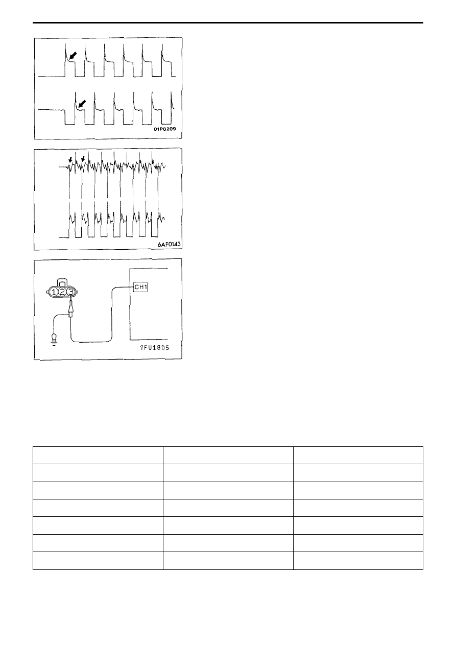
<Abnormal waveform>
• Example 1
Waveform characteristics
Motor turning induced electromotive force is absent.
Cause of fault
Motor malfunction (motor is not turning)s
• Example 2
Waveform characteristics
Current is not supplied to the motor coil on the open circuit side. (Voltage
does not drop to 0V).
Furthermore, the induced electromotive waveform on the normal side is
slightly different to the standard waveform.
Cause of fault
Circuit is broken between the motor and engine ECU.
10-5 Ignition coil (power transistor control signal)
<Measurement Method>
(1) Undo ignition coil connector, then connect special harness
(MBB991658). (All terminals should be connected)
(2) Connect oscilloscope probe to ignition coil connector terminal No.3.
Note
When doing engine ECU connector measurement, connect the
oscilloscope probe to terminal No.11 (Ignition coil Nos.1 and 4), terminal
No.12 (Ignition coil Nos.2 and 3).
(3) To check ignition advance condition, simultaneously observe crank
angle sensor output signal.
<Standard waveform>
Observation conditions
Open
circuit
side
Normal
side
Oscilloscope
Power transistor control signal
Crank angle sensor
Probe switch
x1
x1
AC-GND-DC
DC
DC
VOLTS/DIV.
2V
2V
TIME/DIV.
10ms
10ms
Other
-
-
Engine speed
About 1,200 rpm