Mitsubishi Lancer Evolution 8. Manual - part 173


  Index      Mitsubishi     Mitsubishi Lancer Evolution 8 - service repair manual


Search            


Content   ..  171  172  173  174   ..


Mitsubishi Lancer Evolution 8. Manual - part 173


MPI – TROUBLESHOOTING

13A-78

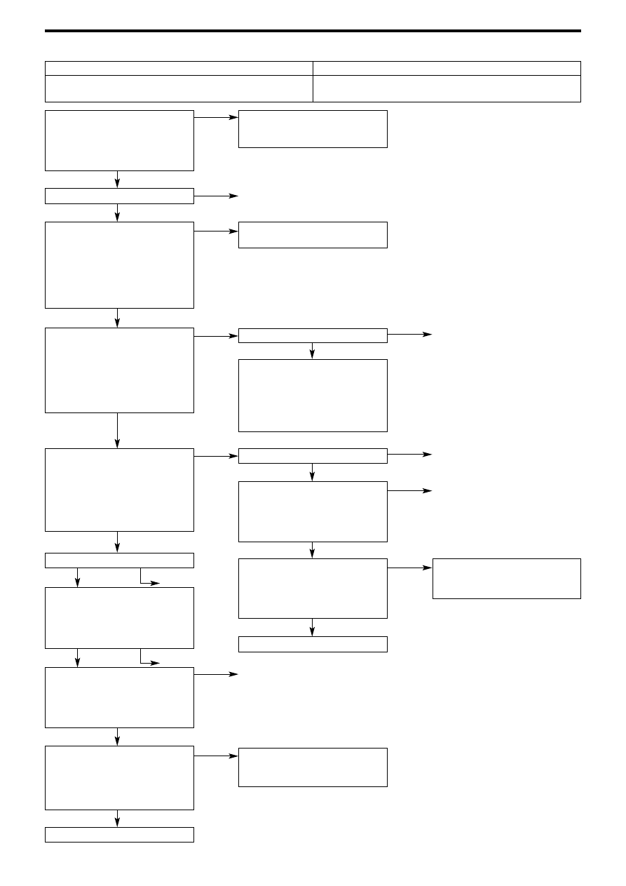
Checking Procedure 33

MUT-II/III Actuator Test
• No.12: Waste gate solenoid

valve

OK: Operating noise audible,

vibrates

Check connector B-30

B-30 Waste gate solenoid valve
connector measurement
• Undo connector, then take

measurement on solenoid valve
side

• Resistance across 1– 2
OK: 29 to 35Ω (at 20°C)

B-30 Waste gate solenoid valve
connector measurement 
• Undo connector, then take

measurement on harness side

• Ignition switch: ON
• Resistance across 1 - earth
OK: Battery voltage

C-50 Engine ECU connector
measurement
• Engine ECU terminal voltage

measurement

• Ignition switch: ON
• Voltage across 41 – earth
OK: Battery voltage

Check connector C-50

Check and repair harness
between waste gate solenoid
valve and engine ECU
• Check to see if output wire is

damaged

Check and repair harness
between waste gate solenoid
valve and engine control relay
• Check to see if power supply

cable is damaged

MUT-II/III Actuator Test
• No.12: Secondary air control

solenoid valve

OK: Operating noise audible,

vibrates

Replace engine ECU

Intermittent malfunction (ref.
Chapter 00 – Intermittent
Malfunctions)

Replace waste gate solenoid
valve

Check connector B-19X

Check and repair harness
between waste gate solenoid
valve and engine control relay
• Check to see if power supply

cable is broken or has a short
circuit

Check connector C-50

Check and repair harness
between waste gate solenoid
valve and engine ECU
• Check to see if output wire is

damaged or has a short circuit

MUT-II/III Actuator Test
• No.12: waste gate solenoid

valve

OK: Operating noise audible,

vibrates

Replace engine ECU

Intermittent malfunction (ref.
Chapter 00 – Intermittent
Malfunctions)

Intermittent malfunction (ref.
Chapter 00 – Intermittent
Malfunctions)

Waste Gate Solenoid Valve System

Probable causes

The waste gate solenoid valve controls pressure that is
introduced to the turbocharger waste gate actuator

• Waste gate solenoid valve malfunction
• Engine ECU malfunction

NG

NG

NG

NG

OK

NG

NG

NG

OK

OK

OK

NG

NG

OK

OK

OK

OK

OK

OK

OK

OK

OK

NG

NG

NG

NG

Repair

Repair

Repair

Repair

Repair

Repair

Repair

MPI – TROUBLESHOOTING

13A-79

Check connector C-50

Check harness between ISC
servo and engine ECU
• Check to see if output wire is

damaged

Check  harness between ISC
servo ~ engine control relay.
• Check to see if power supply

cable is damaged.

Confirm fault symptoms

Replace engine ECU

Replace ISC servo

Check connector B-19X

Check and repair harness
between ISC servo and engine
control relay
• Check to see if power supply

cable is broken or has a short
circuit

Check connector C-50

Check harness between ISC
servo and engine ECU
• Check to see if output wire is

damaged or has a short circuit

Confirm fault symptoms

Replace engine ECU

Intermittent malfunction (ref.
Chapter 00 – Intermittent
Malfunctions)

Intermittent malfunction (ref.
Chapter 00 – Intermittent
Malfunctions)

Check connector B-126

B-126 ISC servo connector
measurement
• Undo connector, then take

measurement on ISC servo side

• Resistance across 1– 2
• Resistance across 2– 3
• Resistance across 4– 5
• Resistance across 5– 6
OK: 28 to 33Ω

B-126 ISC servo connector
measurement
• Undo connector, then take

measurement on harness side

• Ignition switch: ON
• Resistance across 2 – earth
• Resistance across 5 – earth
OK: Battery voltage

C-50 Engine ECU connector
measurement
• Engine ECU terminal voltage

measurement

• Voltage across 14 – earth
• Voltage across 15 – earth
• Voltage across 28 – earth
• Voltage across 29 – earth
OK: Immediately after starting up

of warm engine is completed,
the voltage changes noted
below are repeated
<when using circuit tester>
Battery voltage 


0 and 6V

Checking Procedure 34

Idle speed control (ISC) servo (servo motor)

Probable causes

The engine ECU controls the volume of air intake during
idling, by opening and closing the servo valve in a by-pass
passage.

• ISC servo malfunction
• ISC servo circuit broken, has a short circuit, or poor

connector contact

• Engine ECU malfunction

OK

NG

NG

NG

OK

NG

NG

NG

OK

OK

OK

NG

NG

NG

OK

OK

OK

OK

OK

OK

OK

NG

NG

NG

Repair

Repair

Repair

Repair

Repair

Repair

Repair

MPI – TROUBLESHOOTING

13A-80

Checking Procedure 35

Check intercooler water spray jet
• Ignition switch: ON
• Intercooler water spray switch

(manual): ON
OK: Intercooler water spray
operates

Check intercooler water spray jet
• Undo engine ECU connector 

C-49, then earth 35 terminal

• Ignition switch: ON

OK: Intercooler water spray
operates

Check connector C-220

Check intercooler water spray
relay (ref. Chapter 15 Intake and
Exhaust)

To next page

D-32 Intercooler water spray
switch connector measurement
• Undo connector, then take

measurement on harness side

• Ignition switch: ON
• Voltage across 5 - earth

OK: Battery voltage

Check connector C-22, C-50

Check harness between engine
ECU and intercooler water spray
switch
• Check to see if signal wire is

broken or has short circuit

Replace engine ECU

D-32 Intercooler water spray
switch connector measurement
• Undo connector, then take

measurement on harness side

• Ignition switch: ON
• Voltage across 3, 5 - earth

OK: Battery voltage

Check connector C-22, C-50 

Check harness between engine
ECU and intercooler water spray
switch
• Check to see if signal wire is

broken or has a short circuit

Replace engine ECU

Replace intercooler water spray
relay

Check connector D-32

Check intercooler water spray
switch (ref. Chapter 15 Intake and
Exhaust)

Check harness between
intercooler water spray switch
and engine ECU
• Check signal wire for damage

Intermittent malfunction (ref.
Chapter 00 – Intermittent
Malfunctions)

Check connector D-32

Check intercooler water spray
switch (ref. Chapter 15 Intake and
Exhaust)

Check connector C-107

Check harness between
intercooler water spray switch
and engine ECU
• Check earth wire to see if it is

broken or damaged

Check and repair harness
between intercooler water spray
switch and engine ECU
• Check to see if signal wire is

damaged

Intercooler Water Spray Circuit System

Probable causes

• When the intercooler water spray switch (manual) is turned ON, an

intercooler water spray manual ON signal is input to the engine ECU.
When it receives this signal, the engine ECU turns the intercooler
water spray switch ON, runs the intercooler water spray switch motor,
sprays water into the intercooler to cool the intake air, and improves
filling efficiency.

• When the intercooler water spray switch (auto) is turned ON, an

intercooler water spray switch auto ON signal is input to the engine
ECU. When it receives this signal, the engine ECU, during high load
driving conditions, intermittently turns the intercooler water spray relay
ON, runs the intercooler water spray motor, sprays water into the
intercooler to cool the intake air, and improves filling efficiency.

• Intercooler water spray switch malfunction
• Intercooler water spray relay malfunction
• Intercooler water spray motor malfunction
• Intercooler water spray relay circuit broken, short

circuit, or poor connector contact

• Intercooler water spray switch circuit broken, short

circuit, or poor connector contact

• Ignition switch malfunction
• Engine ECU malfunction

OK

OK

OK

OK

OK

OK

OK

OK

OK

NG

NG

NG

NG

NG

NG

NG

OK

OK

OK

NG

OK

OK

NG

NG

NG

OK

NG

NG

NG

NG

OK

OK

Repair

Repair

Repair

Repair

Repair

NG

NG

Repair

Repair

Repair

Repair

Repair

Repair

Repair

MPI – TROUBLESHOOTING

13A-81

From previous page

C-220 Intercooler water spray
relay  connector measurement
• Undo connector, then take

measurement on harness side

• Voltage across 3, 1 - earth

(Ignition switch: ON)
OK: Battery voltage 

C-49 Engine ECU connector
measurement
• Undo connector, then take

measurement on harness side

• Voltage across 35  - earth

(Ignition switch: ON)
OK: Battery voltage

Check connector C-31

Check harness between
intercooler water spray relay  and
intercooler water spray relay
motor
•Check power supply cable to see

if it is broken, has a short circuit,
or is damaged

Check harness between
intercooler water spray relay
motor and earth
• Check to see if earth wire is

broken or damaged

Check connectors C-209, 
C-210, C-201, C-208

Check harness between
intercooler water spray relay  and
ignition switch
• Check to see if power supply

cable broken or damaged

Check harness between
intercooler water spray relay and
engine ECU
•Check to see if signal wire is

damaged

Check connector A-34

Check intercooler water spray
relay motor (ref. Chapter 15
Intake and Exhaust)

Replace engine ECU

Check connectors C-22, C-49

Check connectors C-209, 
C-210, C201, C-208

Check harness between intercooler
water spray relay and ignition switch
• Check to see if power supply cable

is broken or has a short circuit

Check ignition switch
(ref. Chapter 54)

Check connectors C-22, C-208

Check and repair harness
between intercooler water spray
relay  and engine ECU
• Check signal wire to see if

broken or if it has a short circuit

OK

NG

OK

NG

NG

NG

OK

OK

NG

NG

NG

NG

NG

NG

NG

NG

NG

NG

OK

OK

OK

OK

OK

OK

OK

OK

OK

OK

OK

Repair

Repair

Repair

Repair

Repair

Repair

Repair

Repair

Repair

Repair

Repair

Repair


Content   ..  171  172  173  174   ..