Mitsubishi Lancer Evolution 8. Manual - part 99


  Index      Mitsubishi     Mitsubishi Lancer Evolution 8 - service repair manual


Search            


Content   ..  97  98  99  100   ..


Mitsubishi Lancer Evolution 8. Manual - part 99


MANUAL TRANSMISSION - TRANSMISSION

22-21

Checks

M1222001100123

Reversing light switch
1. Check current between terminals.

Item

Live

Press switch

Yes

Release switch

No

2. If there is a fault, check the reversing light switch.

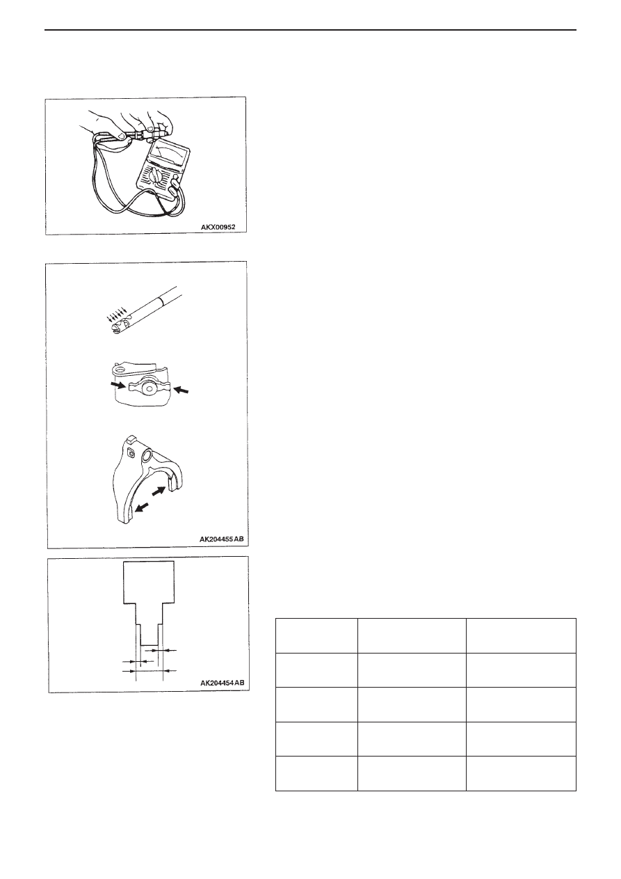
Fork rod / Reverse lever assembly / Shift fork
1. Check for wear, scratches, warping or other

abnormalities on contact and sliding surfaces. If
anything is abnormal replace that part (if the only
problem is extent of contact,  replacement is not
necessary).

2. Check width of claws on shift fork (section that

slides against coupling sleeve), make sure it is not
above  the limit.

Item

Limit for wear
on 1 side (mm)

Sliding width
when new (mm)

1st-2nd gear

0.2

7.80 to 7.93

3rd-4th gear

0.2

7.80 to 7.93

5th-6th gear

0.2

6.10 to 6.23

Reverse

0.2

12.80 to 12.93

Fork rod

Reverse lever assembly

Shift fork

Sliding width
when new

Wear on one side

Wear on one side

MANUAL TRANSMISSION -  INPUT SHAFT

22-22

INPUT SHAFT

Dismantling / Assembling

Dismantling Order

Dismantling Order (cont.)

<<A>> 

>>K<<

1.  Input shaft rear bearing

<<D>>

17. 4th gear

>>J<<

2.  Snap ring

<<D>>

18. Needle roller bearing

<<B>>

>>I<<

3.  6th gear sleeve

<<D>>

>>D<<

19. 4th gear sleeve

<<B>>

4.  Needle roller bearing

<<D>>

20. Synchroniser ring

<<B>>

5. 6th 

gear

<<D>>

>>C<<

21. 

3rd-4th 

gear 

6.  Synchroniser ring

synchroniser assembly

<<C>>  >>H<<

7.  5th-6th gear synchroniser assembly

>>B<<

22. Synchroniser spring

>>G<<

8.  Synchroniser spring

>>B<<

23. Synchroniser sleeve

>>G<<

9.  Synchroniser sleeve

>>B<<

24. Synchroniser key

>>G<<

10. Synchroniser key

>>B<<

25. 3rd-4th gear

>>G<<

11. 5th-6th gear synchroniser hub

synchroniser hub

<<C>>

12. Synchroniser ring

<<D>>

26. Synchroniser outer ring

<<C>>

13. 5th gear

<<D>>

27. Synchroniser cone

14. Needle roller bearing

<<D>>

28. Synchroniser inner ring

<<D>>

>>F<<

15. 5th gear sleeve

<<D>>

29. 3rd gear

<<D>>

>>E<<

16. Thrust washer

30. Needle roller bearing

<<E>>

>>A<<

31. Ball bearing
32. Input shaft

Apply gear oil to all
sliding sections
when fitting

MANUAL TRANSMISSION -  INPUT SHAFT

22-23

Key Points for Dismantling

<<A>> Removing input shaft rear bearing
Using the bearing remover (Special tool No.
MD998801), remove input shaft rear bearing.

<<B>> Removing 6th gear sleeve / needle
bearing / 6th gear
Fit the bearing remover (Special tool No.
MD998917) to the 6th gear and remove 6th gear
sleeve, needle bearing and 6th gear.

<<C>> Removing 5th-6th gear synchroniser
assembly / synchroniser ring / 5th gear
Fit the bearing remover (Special tool No.
MD998917) to the 5th gear and remove 5th-6th gear
synchroniser assembly, synchroniser ring and 5th
gear.

<<D>> Removing 5th gear sleeve / thrust washer
/ 4th gear/ needle bearing / 4th gear sleeve / 3rd-
4th gear synchroniser assembly / synchroniser
outer ring / synchroniser cone / synchroniser
inner ring / 3rd gear
Fit the bearing remover (Special tool No.
MD998917) to the 3rd gear and remove 5th gear
sleeve, thrust washer, 4th gear, needle bearing, 4th
gear sleeve, 3rd-4th gear synchroniser assembly,
synchroniser outer ring, synchroniser cone,
synchroniser inner ring, and 3rd gear.

MANUAL TRANSMISSION -  INPUT SHAFT

22-24

<<E>> Removing ball bearing
Using the bearing remover (Special tool No.
MD998801), remove ball bearing.

Key Points for Assembly

>>A<< Fitting ball bearing
Fit ball bearing, using the following special tools:
• Installer cap (MD998812)
• Installer 100 (MD98813)
• Installer adaptor (MD998818)

>>B<< Fitting 3rd-4th gear synchroniser hub /
synchroniser key / synchroniser sleeve /
synchroniser spring

Synchroniser hub must not be re-used.
1. Join 3rd-4th gear synchroniser hub and

synchroniser sleeve in direction shown in
drawing.

Do not fit the central protrusions from the 2
synchroniser springs into the same
synchroniser key.
2. Fit synchroniser keys and springs in positions as

shown in the drawing.

4th gear 

3rd gear

4 oil grooves

3 oil grooves

Distinguishing
groove

Central
protrusion

Central
protrusion

Care required

Care required


Content   ..  97  98  99  100   ..