Mitsubishi Lancer Evolution 7. Manual - part 297
POWER PLANT MOUNT - Transmission Mounting
32-5
TRANSMISSION MOUNTING
REMOVAL AND INSTALLATION
Caution
*: Indicates parts which should be initially tightened, and then fully tightened after placing the
vehicle horizontally and loading the full weight of the engine on the vehicle body.
Pre-removal Operation
D
Under Cover Removal (Refer to GROUP 51 - Front
Bumper.)
D
Raise the engine and transmission assembly until
its weight is not applied to the insulator, and support
it securely.
D
Battery and Battery Tray Removal
D
Air Cleaner Removal (Refer to GROUP 15.)
D
Radiator Removal (Refer to GROUP 14.)
D
Air Pipe C, Air By-pass Hose, Air Hose D Removal
(Refer to GROUP 15 - Inter Cooler.)
D
Rear Roll Stopper Removal (Refer to P.32-6.)
Post-installation Operation
D
Rear Roll Stopper Installation (Refer to P.32-6.)
D
Air Pipe C, Air By-pass hose, Air Hose D Installation
(Refer to GROUP 15.)
D
Radiator Installation (Refer to GROUP 15.)
D
Air Cleaner Installation (Refer to GROUP 15.)
D
Battery and Battery Tray Installation
D
Under Cover Installation (Refer to GROUP 51 -
Front Bumper.)
47
±
7 N·m
*
3
3
82
±
7 N·m
*
2
1
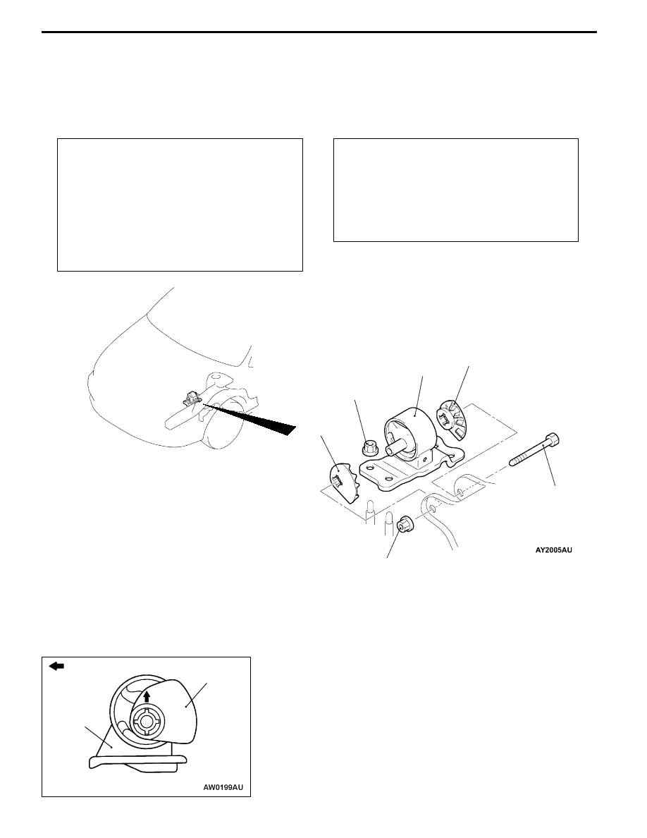
Removal steps
1. Transmission mounting connecting
bolt
2. Transmission mounting
"
AA 3. Transmission mounting stopper
INSTALLATION SERVICE POINT
"
AA TRANSMISSION MOUNT STOPPER
INSTALLATION
Install the transmission mount stopper so that its arrow points
upward.
INSPECTION
Check the transmission mounting insulator for cracks,
separation or deformation.
Engine side
Transmission
mount bracket
Transmission
mount stopper