Mitsubishi Lancer Evolution 7. Manual - part 213


  Index      Mitsubishi     Mitsubishi Lancer Evolution 7 - service repair manual


Search            


Content   ..  211  212  213  214   ..


Mitsubishi Lancer Evolution 7. Manual - part 213


FUEL SUPPLY - On-vehicle Service/Fuel tank

13B-3

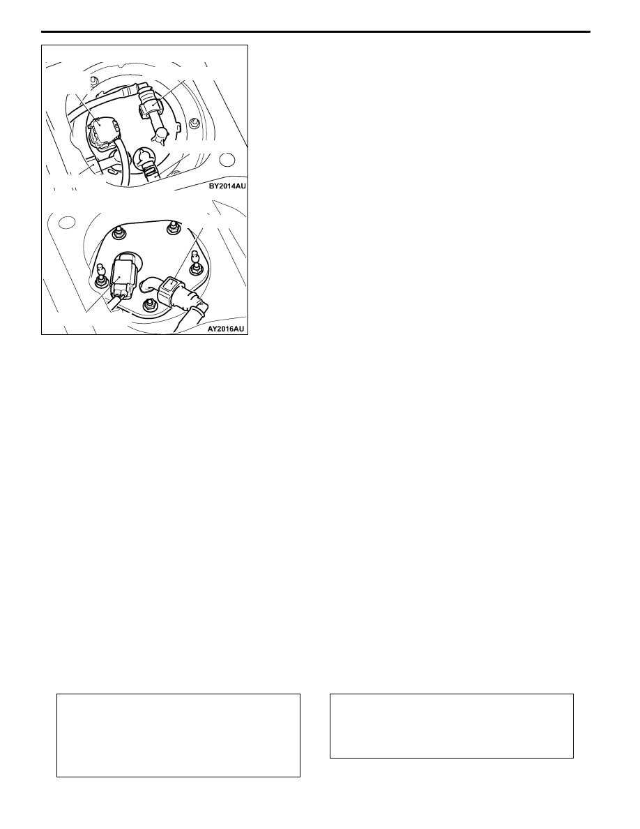
FUEL PUMP AND GAUGE ASSEMBLY, PIPE

AND GAUGE ASSEMBLY (FUEL GAUGE UNIT)

1. Remove the rear seat cushion assembly.

(Refer to GROUP 52A.)

2. Remove the service hole cover.

3. Disconnect the harness connector, high-pressure fuel

tube, suction hose, and return hose.

4. Unscrew the mounting nuts to remove the fuel pump

and gauge assembly or pipe and gauge assembly.

5. Fuel gauge unit check. (Refer to GROUP 54 -

Combination Meter.)
NOTE

If the inspection shows that the basic resistance and

the height of float are out of the standard value, replace

the gauge unit.

(Refer to P.13B-8.)

6. Install the fuel pump and gauge assembly or pipe and

gauge assembly.

Tighten the mounting nuts to the

specified torque.

Specified torque: 2.5

± 0.5 N·m

7. Connect the harness connector, high-pressure fuel tube,

suction hose, and return hose.
Caution

(1) Snap the high-pressure fuel hose or suction hose

one-touch joint into place, then pull back slightly

on the hose to assure it is securely fitted. However,

the connection should have a play of approx. 3

mm.

(2) Insert the return hose for 20 - 30 mm for

connection.

8. Install the rear seat cushion assembly.

(Refer to GROUP 52A.)

FUEL TANK

REMOVAL AND INSTALLATION

Pre-removal Operation
D

Draining Fuel

D

Fuel Pump Connector Disconnection

(How To Reduce Fuel Pressure)

(Refer to GROUP 13A - On-vehicle Service.)

D

Center Exhaust Pipe Removal

(Refer to GROUP 15.)

Post-installation Operation
D

Center Exhaust Pipe Removal

(Refer to GROUP 15.)

D

Refilling Fuel

D

Checking for Fuel Leaks

High-pressurefuel tube

Harness

connector

Suction hose

Return hose

Suction hose

Harness connector

<Fuel pump and gauge assembly>

<Pipe and gauge assembly>

FUEL SUPPLY - Fuel Tank

13B-4

<Fuel tank assembly>

12

10

6

21

1

2

4

7

8

9

15

18

23

20

13

3

14

22

24

11

19

5

16

17

5

2.5 ± 0.5 N·m

2.5 ± 0.5 N·m

26 ± 4 N·m

22 ± 4 N·m

Removal steps <Fuel tank assembly>

1. Filler neck pipe, Filler neck vapour

pipe connection

2. Vapour pipe connection

3. Main pipe connection

4. Return pipe connection

D

Parking brake

cable clamp (LH)

connection (Refer to GROUP 36.)

D

Rear wheel speed sensor (RH)

connection

(Refer to GROUP 35 - Wheel speed

sensor.)

D

Rear wheel speed sensor harness

connector connection

(Refer to GROUP 35 - Wheel speed

sensor.)

A

A"

5. Harness connector connection

A

A"

6. Fuel tank assembly

7. Fuel tank protector

"

AA 8. Suction hose

"

AA 9. High-pressure fuel hose

10. Fuel tank pipe assembly

"

AA 11. High-pressure fuel hose

"

BA 12. Fuel tank return hose

13. Return hose

14. Fuel tank vapour hose

15. Check valve

16. Vapour hose

17. Pipe and gauge assembly

18. Plate

19. Fuel pump and gauge assembly

20. Parking

21. Fuel cut off valve assembly

22. Parking

23. Filler neck hose

24. Filler neck vapour hose

FUEL SUPPLY - Fuel Tank

13B-5

<Fuel filler neck assembly>

30

31

28

25

29

26

27

24 ± 4 N·m

Removal steps <Filler neck assembly>

25. Filler neck protector

26. Filler neck hose connection

27. Filler neck vapour hose connection

28. Fuel filler cap

29. Fuel filler neck assembly

30. Fuel shut-off valve

31. Parking

REMOVAL SERVICE POINT

A

AHARNESS CONNECTOR CONNECTION/FUEL

TANK ASSEMBLY DISCONNECTION

1. Remove the differential support member and tilt the

differential carrier.

(Refer to GROUP 27B.)

2. Hold the fuel tank with a transmission jack and remove

the nut connected to the fuel tank.

3. Tilt the fuel tank to allow access with a hand and disconnect

the harness connector.

4. Remove the fuel tank in the tilting direction to avoid contact

with the differential carrier.

Fuel tank

Floor

Differntial carrier

Removal

direction

Tilt

FUEL SUPPLY - Fuel Tank

13B-6

INSTALLATION SERVICE POINT

"

AHIGH-PRESSURE FUEL HOSE/SUCTION HOSE

INSTALLATION

Caution

Snap the high-pressure fuel hose or suction hose

one-touch joint into place, then pull back slightly on the

hose to assure it is securely fitted.

However, the

connection should have a play of approx. 3 mm.

"

BFUEL TANK RETURN HOSE INSTALLATION

Caution

Insert the return hose for 20 - 30 mm for connection.

3 mm

Corresponding

side

High-pressure fuel tube


Content   ..  211  212  213  214   ..