Mitsubishi Lancer Evolution 7. Manual - part 171
ENGINE OVERHAUL -
Piston and Connecting Rod
11B-61
4. If there is no identification, measure the oil clearance
and select.
"
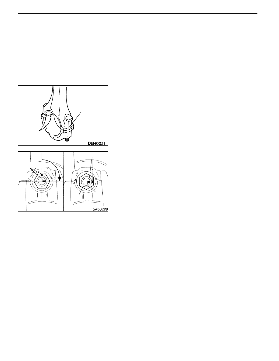
FA CONNECTING ROD CAP INSTALLATION
1. Align the marks made during disassembly, and install
the bearing cap onto the connecting rod. When using
a new connecting rod that has no match marks, assemble
so that the bearing rotation-preventing notch comes to
the same side as shown in the illustration.
2. The plasticity range tightening method is adopted for the
connecting rod bolt and nut, so elongate and inspect
the bolt before reusing it.
Inspect that the bolt is elongated to the extent that the
nut can be screwed onto the last thread when screwed
by hand. If the nut cannot be screwed on smoothly to
the end, the bolt threads are elongated and the bolt must
be replaced.
3. Apply engine oil on the nut’s threads and seat surface
before installing the nut.
4. After installing each nut onto the bolt with fingers,
alternately tighten the nuts to assemble the cap correctly.
5. Tighten the nut at a 20 N•m torque.
6. Make a paint mark on the head of the nut.
7. Using the position of the mark painted on the nut as
reference, make paint marks on the bolt at the 90_ to
94_ positions in the nut tightening direction.
8. Tighten the nut between 90_ and 94_, and confirm that
the paint marks on the nut and bolt match.
Caution
If the tightening angle is less than 90_, the connection
performance may not be attained, so take special
care to the tightening angle when tightening.
If the tightening angle is larger than 94_, completely
loosen the nut and start again from step 1.
Cylinder No.
Rotation-
preventing
notch
Paint marks
90_ - 94_
Paint marks
Nut
Bolt