Mitsubishi Lancer Evolution 7. Manual - part 28
BODY -
Main Body
4-3
MAIN BODY
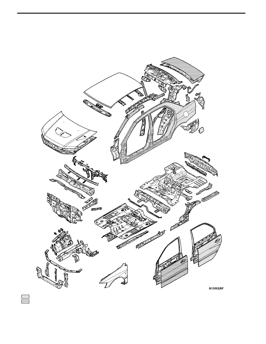
BODY PANELING
The body has been given enhanced impact safety performance. It has been made lighter by adopting
aluminum alloy panels for the hood panel and front fender.
: High-tensile steel panels
: Anti-corrosion steel panels