Mitsubishi Eclipse. Manual - part 677
IGNITION SYSTEM
TSB Revision
ENGINE ELECTRICAL
16-51
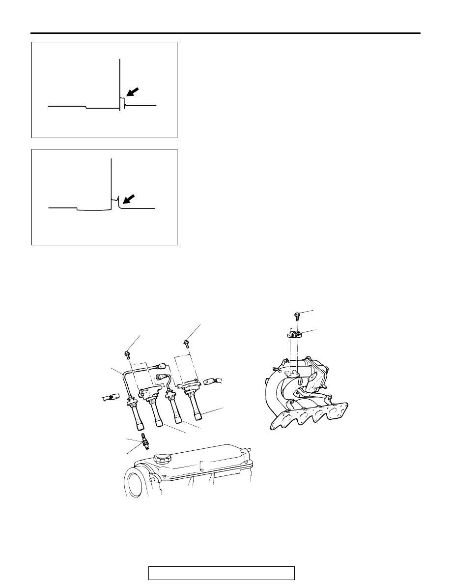
Example 4
• Wave characteristics
Spark line is high and short
• Cause of problem
Spark plug cable is not properly connected. (Causing a
dual ignition)
Example 5
• Wave characteristics
No waves in wave damping section
• Cause of problem
Layer short in ignition coil.
IGNITION COIL
REMOVAL AND INSTALLATION <2.4L ENGINE>
M1163004000396
AKX00291
AKX00292
AC000288
1
2
3
1
2
4
9.8 ± 2.0 N·m
87 ± 17 in-lb
9.8 ± 2.0 N·m
87 ± 17 in-lb
4.9 ± 1.0 N·m
44 ± 8 in-lb
25 ± 4 N·m
18 ± 3 ft-lb
AB
REMOVAL STEPS
1.
SPARK PLUG CABLE
2.
IGNITION COIL ASSEMBLY
3.
SPARK PLUG
4.
IGNITION FAILURE SENSOR
ASSEMBLY
REMOVAL STEPS (Continued)