Mitsubishi Eclipse. Manual - part 669


  Index      Mitsubishi     Mitsubishi Eclipse - service repair manual 2004 year


Search            


Content   ..  667  668  669  670   ..


Mitsubishi Eclipse. Manual - part 669


CHARGING SYSTEM

TSB Revision

ENGINE ELECTRICAL

16-19

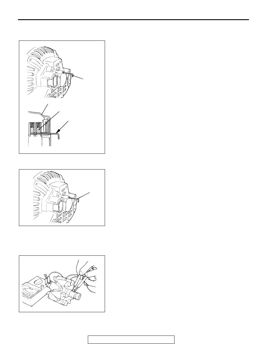
ASSEMBLY SERVICE POINTS

.

>>A<< REGULATOR ASSEMBLY INSTALLATION
After installing the regulator assembly, insert a wire through the 
hole provided on the rear bracket while pressing down on the 
brush, and secure the brush.
NOTE: By inserting a wire, the brush will be secured in place, 
and the installation of the rotor will be easier.

.

>>B<< ROTOR ASSEMBLY INSTALLATION
After installing the rotor, remove the wire used to secure the 
brush.

INSPECTION

M1161001700022

.

ROTOR CHECK
1. Check the continuity between the slip rings of the field coil. If 

the resistance value is not within the standard value, replace 
the rotor.

Standard value: approximately 2 

 5 

AKX00358

WIRE

REAR BRACKET

BRUSH

WIRE

AB

AKX00359

WIRE

AB

AKX00360

CHARGING SYSTEM

TSB Revision

ENGINE ELECTRICAL

16-20

2. Check the continuity between the slip ring and the core. If 

there is continuity, replace the rotor.

.

STATOR CHECK
1. Check the continuity between the coil lead. If there is no 

continuity, replace the stator.

2. Check the continuity between the coil and the core. If there 

is continuity, replace the stator.

.

RECTIFIER CHECK
1. Check the continuity between the positive rectifier and the 

stator coil lead connection terminal with a tester. If there is 
continuity between the terminals, the diode is shorted, so 
replace the rectifier.

AKX00361

AKX00362

AKX00363

AKX00364

CHARGING SYSTEM

TSB Revision

ENGINE ELECTRICAL

16-21

2. Check the continuity between the negative rectifier and the 

stator coil lead connection terminal with a tester. If there is 
continuity between the terminals, the diode is grounded, so 
replace the rectifier.

3. Check the continuity of the three diodes by connecting an 

ohmmeter to both ends of each diode. If there is continuity 
between the directions, or if there is no continuity, the diode 
is damaged, so replace the rectifier.

.

BRUSH CHECK
1. Replace the brush if the brush protrusion length shown in 

the illustration is below the minimum limit value.

Minimum limit: 2 mm (0.08 inch)

2. The brush can be removed by unsoldering the brush lead 

wire.

3. When installing a new brush, push the brush in to the brush 

holder, and solder the lead wire.

AKX00365

AKX00366

AKX00367AB

PROTRUSION
LENGTH

AKX00368

SOLDERED

AB

STARTING SYSTEM

TSB Revision

ENGINE ELECTRICAL

16-22

STARTING SYSTEM

GENERAL DESCRIPTION

M1162000100194

If the ignition switch is turned to the "START" posi-
tion, current flows in the coil provided inside mag-
netic switch, attracting the plunger. When the plunger 
is attracted, the lever connected to the plunger is 
actuated to engage the starter clutch.
On the other hand, attracting the plunger will turn on 
the magnetic switch, allowing the "B" terminal and 
"M" terminal to conduct. Thus, current flows to 
engage the starter motor.

When the ignition switch is returned to the "ON" posi-
tion after starting the engine, the starter clutch is dis-
engaged from the ring gear.
An overrunning clutch is provided between the pinion 
and the armature shaft, to prevent damage to the 
starter.

OPERATION

• For models equipped with M/T, the clutch pedal 

position switch contact is switched OFF when the 
clutch pedal is depressed. When the ignition 
switch is then switched to the "ST" position, elec-
tricity flows to the starter relay and the starter 
motor, the contact (magnetic switch) of the starter 
is switched ON and the starter motor is activated.

NOTE: If the ignition switch is switched to the 
"ST" position without the clutch pedal being 
depressed, electricity flows to the starter relay 
(coil), the clutch pedal position switch (contacts) 
and to ground, with the result that the contacts of 
the starter relay are switched OFF, and because 
the power to the starter motor is thereby inter-
rupted, the starter motor in not activated.

AKX00196

PULL-IN COIL

HOLDING
COIL

PLUNGER

LEVER

PINION SHAFT

OVERRUNNING
CLUTCH

YOKE

BRUSH

ARMATURE

IGNITION
SWITCH

BATTERY

+

AB


Content   ..  667  668  669  670   ..