Mitsubishi Eclipse. Manual - part 660


  Index      Mitsubishi     Mitsubishi Eclipse - service repair manual 2004 year


Search            


Content   ..  658  659  660  661   ..


Mitsubishi Eclipse. Manual - part 660


INTAKE MANIFOLD PLENUM

TSB Revision

INTAKE AND EXHAUST

15-11

INSTALLATION SERVICE POINT

.

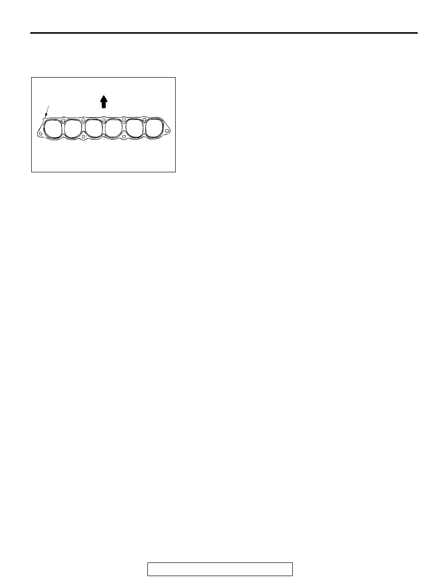
>>A<< INTAKE MANIFOLD PLENUM GASKET INSTALLA-
TION
Install the gasket with the protrusion in the position illustrated.

AC001424

PROTRUSION

FRONT OF
VEHICLE

AB

INTAKE MANIFOLD <2.4L ENGINE>

TSB Revision

INTAKE AND EXHAUST

15-12

INTAKE MANIFOLD <2.4L ENGINE>

REMOVAL AND INSTALLATION

M1151003000705

Pre-removal Operation
• Fuel Discharge Prevention [Refer to GROUP 13A, 

On-vehicle Service 

− Fuel Pump Relay Disconnection 

(How to Reduce Pressurized Fuel Lines) 

P.13A-932

.]

• Engine Coolant Draining [Refer to GROUP 00, Mainte-

nance Service 

− Engine Coolant (Change) 

P.00-58

.]

• Air Cleaner Removal (Refer to 

P.15-6

.)

• Throttle Body Removal (Refer to GROUP 13A, Throttle 

Body 

P.13A-945

.)

• Thermostat Case Assembly Removal (Refer to GROUP 

14, Water Hose and Water Pipe 

P.14-28

.)

Post-installation Operation
• Thermostat Case Assembly Installation (Refer to GROUP 

14, Water Hose and Water Pipe 

P.14-28

.)

• Throttle Body Installation (Refer to GROUP 13A, Throttle 

Body 

P.13A-945

.)

• Air Cleaner Installation (Refer to 

P.15-6

.)

• Engine Coolant Supplying [Refer to GROUP 00, Mainte-

nance Service 

− Engine Coolant (Change) 

P.00-58

.]

• Fuel Leakage Inspection

AC006143 AB

ENGINE OIL

O-RING

FUEL RAIL

8

9

6

1

2

7

10

11

5

8

4

3

4.9 ± 1.0 N·m
44 ± 8 in-lb

12 ± 2 N·m
100 ± 22 in-lb

14 ± 1 N·m
117 ± 13 in-lb

(ENGINE OIL)

N

N

REMOVAL STEPS

1. PURGE HOSE CONNECTION
2. BRAKE BOOSTER VACUUM HOSE 

CONNECTION

3. IGNITION COIL CONNECTOR
4. INJECTOR CONNECTOR
5. MANIFOLD ABSOLUTE PRESSURE 

SENSOR CONNECTOR

6. EVAPORATIVE EMISSION PURGE 

SOLENOID VALVE CONNECTOR

7. EGR VACUUM REGULATOR 

SOLENOID VALVE CONNECTOR

>>A<<

8. FUEL HIGH-PRESSURE HOSE 

CONNECTION

9. FUEL RETURN HOSE 

CONNECTION

10. OIL DIPSTICK AND DIPSTICK 

GUIDE

11. PRESSURE HOSE CONNECTION

REMOVAL STEPS (Continued)

INTAKE MANIFOLD <2.4L ENGINE>

TSB Revision

INTAKE AND EXHAUST

15-13

REMOVAL SERVICE POINT

.

<<A>> FUEL RAIL, INJECTOR AND FUEL PRESSURE REG-
ULATOR REMOVAL

CAUTION

Care must be taken when removing the fuel rail not to drop 
the injector.
Remove the fuel rail with the injectors and pressure regulator 
attached to it.

AC006039

4.9 ± 1.0 N·m
44 ± 8 in-lb

11 ± 1 N·m
98 ± 8 in-lb

20 ± 2 N·m
14 ± 2 in-lb

12 ± 1 N·m
100 ± 13 in-lb

4.9 ± 1.0 N·m
44 ± 8 in-lb

8.9 ± 1.9 N·m
78 ± 17 in-lb

30 ± 3 N·m
23 ± 2 in-lb

8.8 ± 1.0 N·m
78 ± 9 in-lb

21 ± 4 N·m
16 ± 3 in-lb

8.8 ± 1.0 N·m
78 ± 9 in-lb

11 ± 1 N·m
98 ± 8 in-lb

12

13

14

15

16

17

18

19

20

21

22

23

24

25

26

N

N

N

AC

REMOVAL STEPS

12. PCV HOSE
13. FUEL RETURN PIPE
14. FUEL HOSE

<<A>>

15. FUEL RAIL, INJECTOR AND FUEL 

PRESSURE REGULATOR

16. INSULATOR
17. VACUUM PIPE
18. EGR VALVE
19. INTAKE MANIFOLD
20. INTAKE MANIFOLD GASKET

21. INTAKE MANIFOLD STAY
22. MANIFOLD ABSOLUTE PRESSURE 

SENSOR

23. VACUUM PIPE
24. EVAPORATIVE EMISSION PURGE 

SOLENOID VALVE

25. EGR VACUUM REGULATOR 

SOLENOID VALVE AND VACUUM 
CONTROL VALVE

26. ACCELERATOR CABLE CLAMP

REMOVAL STEPS (Continued)

INTAKE MANIFOLD <2.4L ENGINE>

TSB Revision

INTAKE AND EXHAUST

15-14

INSTALLATION SERVICE POINT

.

>>A<< FUEL HIGH-PRESSURE HOSE INSTALLATION

CAUTION

Be careful not to allow any engine oil to enter the fuel rail.
1. When connecting the fuel high-pressure hose to the fuel rail, 

apply a small amount of new engine oil to the O-ring and 
then insert the fuel high-pressure hose, being careful not to 
damage the O-ring.

2. While turning the fuel high-pressure hose to the left and 

right, install it to the fuel rail.

3. Check that the injector turns smoothly. If it does not turn 

smoothly, the O-ring may be trapped. Remove the fuel 
high-pressure hose and then re-insert it into the fuel rail and 
check again.

INSPECTION

M1151003100597

Check the following points; replace the part if a problem is 
found.

Intake Manifold Check

1. Check for damage or cracking of any part.
2. Clogging of the negative pressure (vacuum) outlet port, or 

clogging of the exhaust gas recirculation passages.

3. Using a straight edge and feeler gauge, check for distortion 

of the cylinder head installation surface.

Standard value: 0.15 mm (0.006 inch) or less 
Limit: 0.20 mm (0.008 inch)

AC001431

FUEL HIGH-
PRESSURE HOSE

O-RING

FUEL RAIL

AB


Content   ..  658  659  660  661   ..