Mitsubishi Eclipse. Manual - part 487
MULTIPORT FUEL INJECTION (MFI) DIAGNOSIS
TSB Revision
MULTIPORT FUEL INJECTION (MFI) <3.0L>
13B-491
.
CIRCUIT OPERATION
• 5-volt voltage is applied to the fuel tank tempera-
ture sensor output terminal (terminal No. 3) from
the ECM (terminal No. 96) <M/T> or PCM (termi-
nal No. 51) <A/T> via the resistor in the ECM
<M/T> or PCM <A/T>.
• The fuel tank temperature sensor output voltage
increases when the resistance increases and
decreases when the resistance decreases. The
ground terminal (terminal No. 1) is grounded to
the vehicle body.
.
TECHNICAL DESCRIPTION
• The fuel tank temperature sensor converts the
fuel tank temperature to a voltage.
• The ECM <M/T> or PCM<A/T> detects the fuel
tank temperature in the fuel tank with this output
voltage.
.
DESCRIPTIONS OF MONITOR METHODS
Fuel tank temperature sensor output voltage is out of
specified range.
.
MONITOR EXECUTION
Continuous
.
MONITOR EXECUTION CONDITIONS (Other
monitor and Sensor)
Other Monitor (There is no temporary DTC stored
in memory for the item monitored below)
• Not applicable
Sensor (The sensor below is determined to be
normal)
• Engine coolant temperature sensor
• Intake air temperature sensor
.
AK300462
42
43
48
49
50
51
52
53
54
55
56
57
46 45 44
58
59
60
61
62
63
64
65
66
47
41
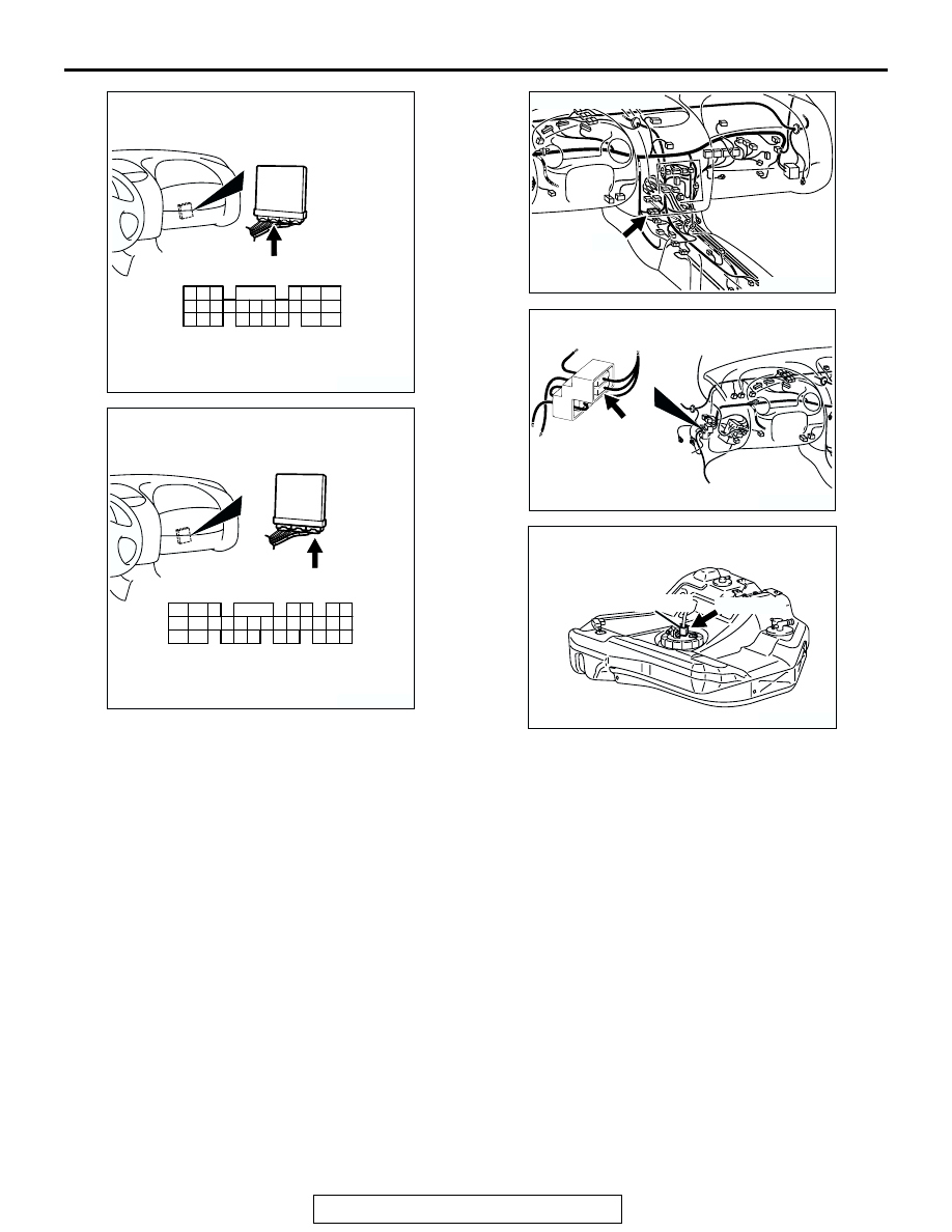
CONNECTOR: C-55 <A/T>
C-55 (GR)
AB
HARNESS CONNECTOR:
COMPONENT SIDE
AK300445
80
87
81
94
85
82
84
93
86
98
99
74
92
73
83
88
91
95
97 96
100
89
78
71
90
76
77
75
72
79
CONNECTOR: C-62 <M/T>
C-62 (GR)
AB
HARNESS CONNECTOR:
COMPONENT SIDE
AK300119
CONNECTOR: C-28
AB
C-28
AK300118
CONNECTOR: C-90
AB
C-90
AK300120AB
D-17 (GR)
CONNECTOR: D-17
FUEL TEMPERATURE
SENSOR
(INTEGRATED IN
FUEL PUMP MODULE)